Nixie Clock - Original Blog Recreated
Date Published: 2010-05-12

Below you will find the mostly preserved original build log for my Nixie Clock formerly posted on thetransistor.com circa 2010. I've also included my original schematics for download. (I've also included some comments in parantheses from present-day me.)
Hello everyone. I’ve designed and built myself a Nixie Tube display, and I’m now going to impart upon the world my build log, schematics (PDF), and Arduino source code. If you have any questions or comments you can email me at tim (at) thetransistor (dot) com. (Yeah, my email is now tim (at) thisdomain these days. Also the schematics and code will be downloadable at the bottom of this page.)
Project Overview
The goal of this project was to create a nixie tube display using one of our Minimalist Arduino kits and some nixie tubes I happened to come across. It has a demo mode to test the tubes, and it also accepts serial inputs to set the display. In the future, I intend to add a second module which will have an atomic clock receiver, and use it as a wall-clock at my apartment, but that’s another story for another page. Here’s a video showing the finished product in all its glory:
And here’s a video with me breifly explaining it:
(No beard! Gods, I was young back then.)
Build Log
It all began with me receiving a pile of nixie tubes abandoned at the Transistor. I resigned myself to figure out how to make a controller and eventually a clock for them.

After doing a bit of research I bought a DC-DC High Voltage Converter from the good folks at All Spectrum Electronics ( http://www.allspectrum.com/ ). (The exact PSU I used is no longer available. Look for something that will take in ~12V and output ~180V DC.)
I then ran some tests on a tube to see if I could control it with an arduino and transistors as shown in the schematics above. Here’s a video result of that test:
You can see that PWM control of the tubes is possible, and could lead to some nifty transition effects later if I stop being so lazy about writing code for it. Anyways, with confirmation that the tubes worked with the power supply and Arduino, I set to work building my circuit, which will now be shown with a series of many many pictures and brief descriptions:
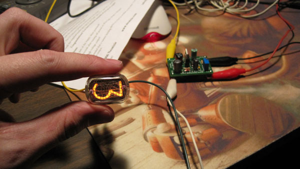
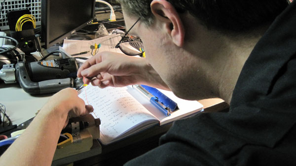
This is a picture from an early test of a tube.
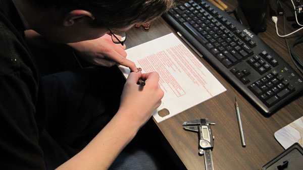

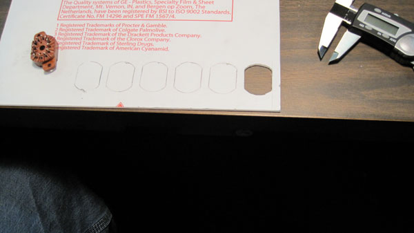
These are me cutting out the Lexan that I will eventually use to mount the Nixie Tubes. I traced the tubes and used a scroll saw to cut out the slots. (It's funny how much easier this part would be with the laser cutter we got a couple years down the line.)

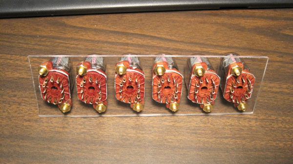
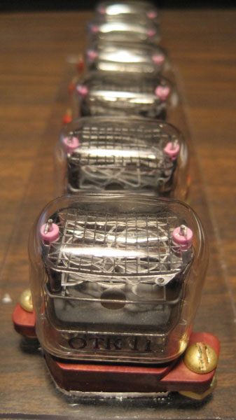
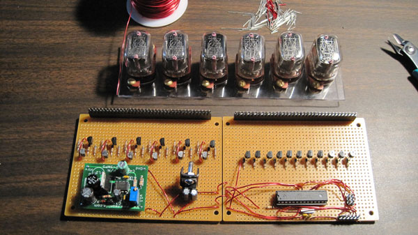
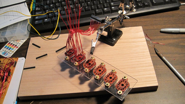
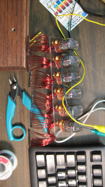
These are pictures of the mounted tubes. You’ll find a pinout from the mounting bracket numbering to tube digits on the schematic drawing above. (Turned out pretty clean without a laser cutter, imo.)
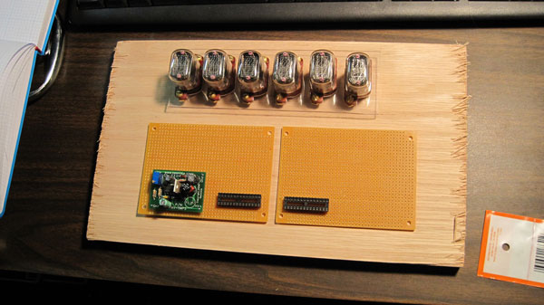
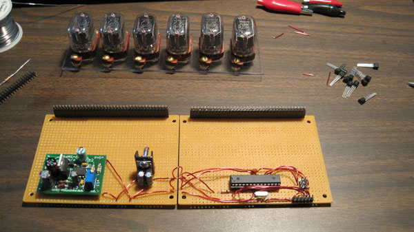
This was an early general idea for the board layout. You’ll note two 28-pin DIP sockets. There’s two because I originally intended to include the clock on the same board as the display, but eventually decided that I’d rather have a versatile display that’ll display anything instead of just a clock, even if that’s what it will end up doing most of the time.
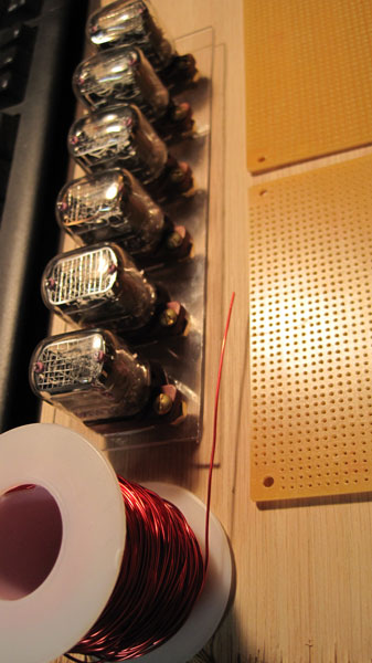
This shows the 20 gauge enamel-coated magnet wire I used to wire up the project. This involved a lot of work getting the enamel off of the wires for soldering. More on that in a bit.
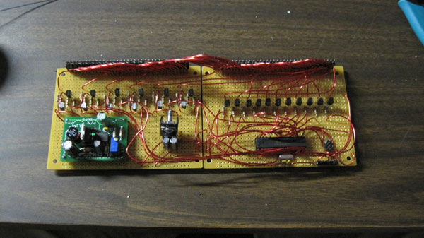
The first things I got working were a simple Minimalist Arduino kit, and the power supplies.


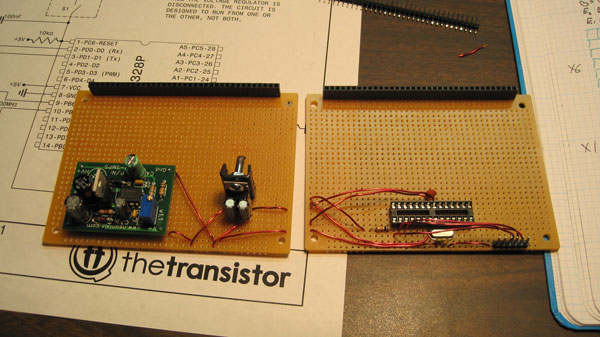
This is a finished Minimalist Arduino on board with the FTDI connector pins working, as well as the 180V power supply circuit board.

I also added an ICSP pinout in case I decide I want to use a bootloader other than the default arduino one in the future. (This came in handy this week when I was updating and getting it back to running properly. None of my FTDI chips seemed to reset the board properly, so I used the ICSP to re-program it with the latest code attached below.)

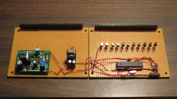
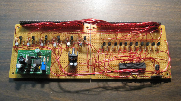
I next added the 11 NPN transistor circuits, as shown here. (This was before I knew places like OSH Park existed, and also before I knew how to use circuitboard CAD programs to make PCBs. Crazy how much work I put into soldering it all manually. You'll also notice the schematic linked at the bottom of the page is drawn in AutoCAD instead of something sensible. Live and learn, I suppose.)


After the NPNs I added the PNP controlled by NPN Darlington arrays to the board, and colored the PNP transistors silver on the top so I wouldn’t have to squint to see which one was NPN and which one was PNP. (That silver sharpie is awesome when working with standard black ICs for just this reason)
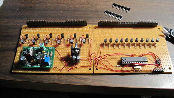
I made the header pinouts at this point, so I could see where all the wires’d line up when connected.

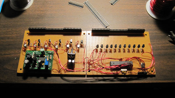

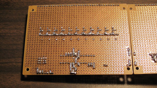
Next I wired all the transistor arrays to the arduino pins. It took a long time, but looked pretty cool when I finished.

With the Arduino wired up, I wanted to test everything and confirm I got it right, and it turns out I did. Huzzah! However, there were miles to go before I rested. Sommat like 288 more wires to solder into place, give or take…
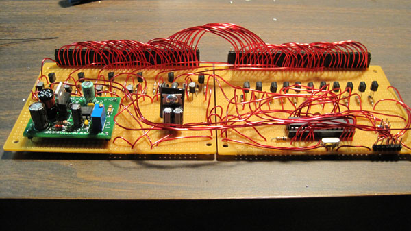
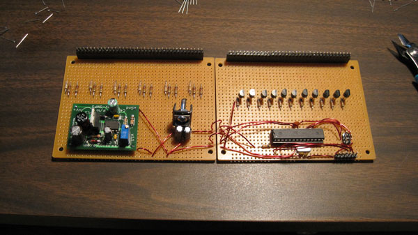
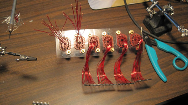
I next wired all the header pins. I really like the way the arched wires turned out.
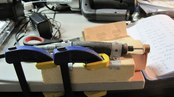

For those interested in how I ground the enamel off all the wires, you can see my dremel apparatus here, which I used to grind the piles of wires used on this project so that they could be soldered. Are there better ways? Probably, but this worked. (In hindsight I should have gotten a lighter and burned it all off.)
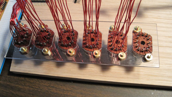
I then ground and soldered 144 more wire ends to the tubes and headers. I also tested often to make troubleshooting problems easier. (These were a bit messier than I originally planned, but I didn't use something like rainbow wire or chopped up IDE cables because I was sold on the enamel wire look.)
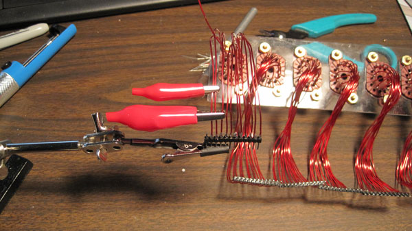
While soldering to the headers, I found a handy method: I took aligator clips, and attached them to the wires that I had already soldered to hold the next wire in place as shown above. It was much easier than trying to set up my helping hands every pin. Food for thought.

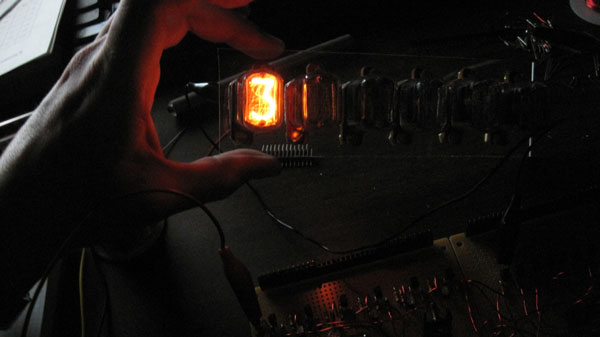
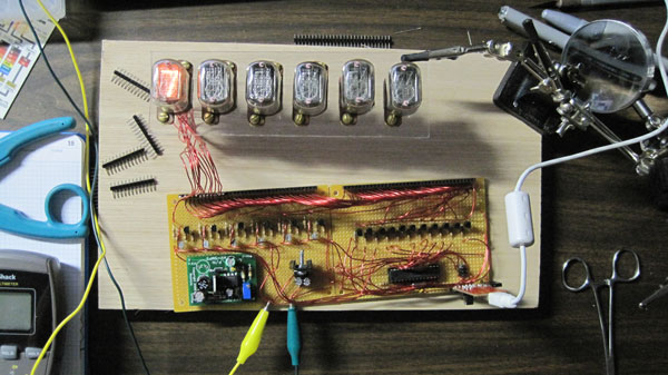
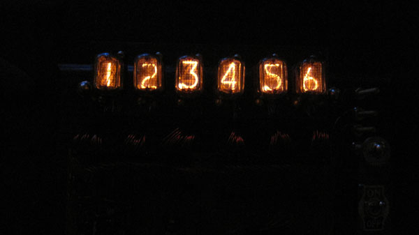
VICTORY! The circuit worked, and I got all the transistors to function. See the video below for my test run of just the working circuit. The rest is more or less just aesthetics, which were important to me for this project. Oh, and programming. Still had plenty of that to do.
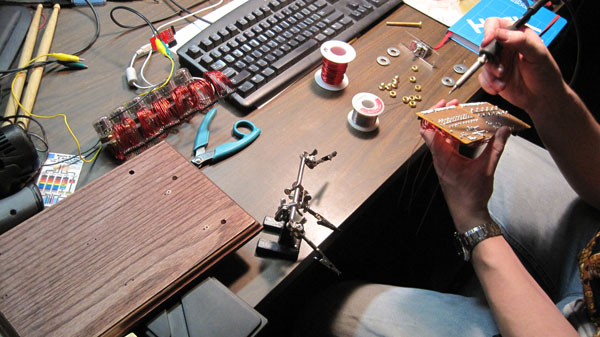
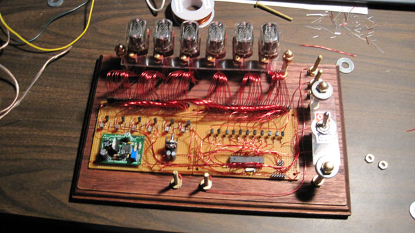
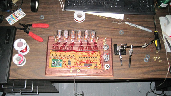
Here’s the assembly pics going on. You can see the stained wood, and some last minute additions to the board (the switch, the brass screws used as pinouts, etc.) piling up. (Ugh, stained oak, with no protective finish. The current woodworking me is still unhappy about that, but it's highly unlikely I'll disassemble the whole clock at this point to replace it with something nicer.)

In the end, everything finally came together. The hardware was done, and only software was left. See the videos at the top for the final product.
With the software finished, the world was my oyster, and the nixie-tube display was complete. Huzzah! (Except for the part where it worked only briefly as a clock, then was used as a countdown timer for a couple New Year's parties, then sat on a shelf collecting a lot of dust for 5-7 years, and only now is it finally returned to being a clock.)
