Date Published: 2025-09-13
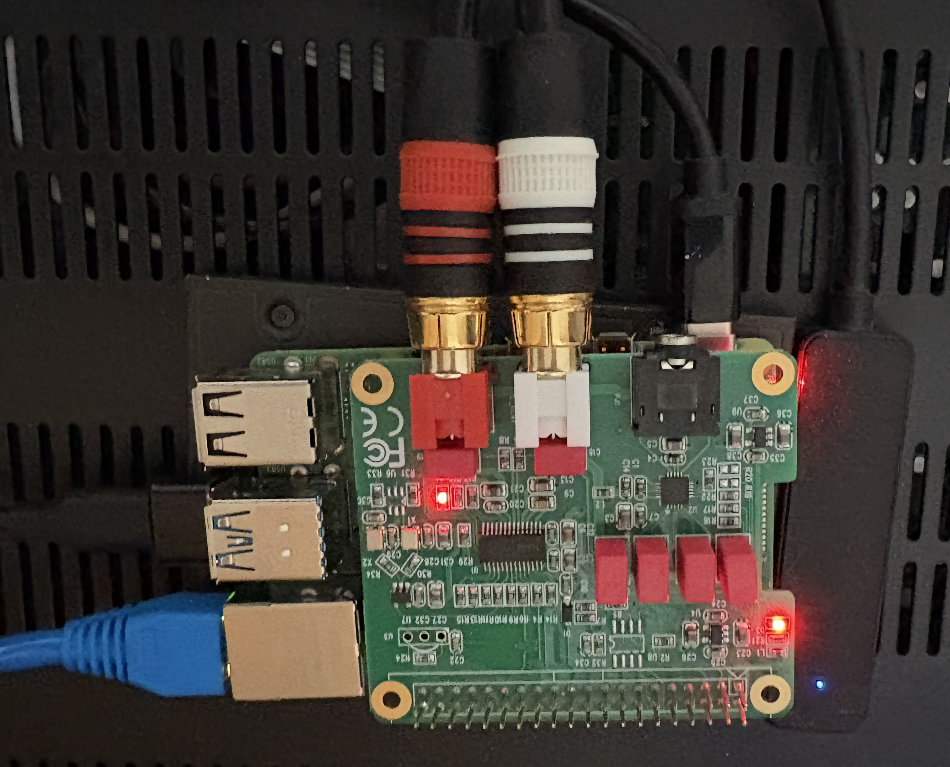
I recently (alright, fine, it was over 2 years ago, and I'm just now getting around to setting it up) decided I wanted to add a Music Player Daemon (MPD) server on a rapberry Pi to my whole-home Audio setup. I'm feeding the Pi's audio into a [Monoprice 6-Zone Home Audio Multizone Controller and Amplifier Kit](https://www.monoprice.com/product?p_id=10761) (which was only $600 when I bought one a few years back, crazy). I had a Raspberry Pi 4B lying around, and I also purchased an [Allo Boss DAC audio hat](https://www.amazon.com/dp/B07D13QWV9) for the Pi. I'm just going to write a blog post of the things I had to modify and work through to get everything set up and working, so if anyone else wants to do the same (or I want to remember how this thing works in a few years) there's some more recent data out there to help out.
oMIDItone - Part 3
Date Published: 2023-11-08
The oMIDItone was progressing steadily through late 2019 into early 2020, and just as everything was finally coming together, this annoying global pandemic called Covid-19 turned up, causing me to become to reclusive hermit and put the whole project into a plastic bin under my desk for the last few years. Unfortunately, I didn't write this blog post at the beginning of the pandemic, so most of the specifics of the process that led to the current state of the project are lost to time. Instead of telling you how I got here, for this blog post I will instead note the current state of the project, and my plans for the future of the oMIDItone.
Utah Hackerspace History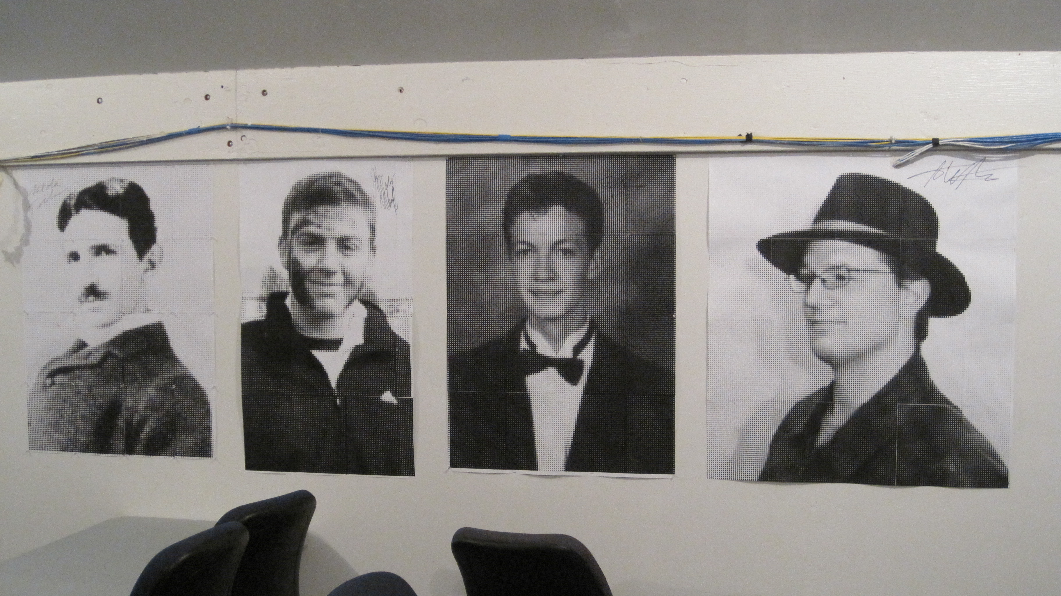
Date Published: 2023-10-03
People are often asking me what I remember from the early days of the local Utah hackerspace scene, so I have decided to put together a blog post that covers the history of the hackerspaces I was involved with since 2009. This is just an overview of the spaces my friends and I founded, and a rough timeline based on my memory, and some quick double-checking of emails to confirm dates were approximately accurate. Circa summer of 2009, d3c4f started a meetup group for a MakeSLC group, based on the then-popular Make Magazine naming convention. Several people showed up, and we met at a warehouse he was renting with Ben (p0wd3r) for the Protocol 42 LAN Gaming group. Eventually we decided to make a hackerspace called HackSLC...
oMIDItone - Part 2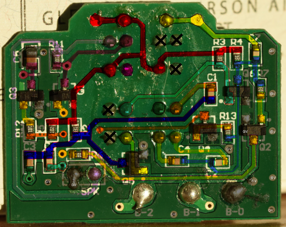
Date Published: 2019-05-10
When last we visited the oMIDItone project the plan was to turn the test code into a class and add more heads to allow for a wider range of pitches to be played at once Sounds simple enough but it took a lot longer than I ever thought it would with many complications and lessons along the way Ill go over everything in roughly the order it happened in starting with code challenges then moving on to hardware challenges and finally the more or less working prototype Hold on to your hats as this post is almost as long as it took me to build the damn thingCodeTurning the code into a class turned out to be fairly straightforward but did lead to some issues I didnt have with just one head The first issue was that when storing an array of bit microsecond note frequency values for every head the Teensy LCs RAM is not large enough to run all heads like I had planned This would eventually necessitate the upgrade to a Teensy but I didnt figure that out until after I had made a terrible PCB for the Teensy LC to run the head design I was planning More on that in the hardware sectionOnce the memory issues were out of the way and I could test with more than one head it became apparent that I was having additional problems with using the original code asis What worked fine with one head running broke down with more than especially at higher frequencies The problem ended up being that my analog sampling using the default library was not fast enough I found this awesome library online and was able to get the sampling rate up high enough to read all heads at once without issue This was done by lowering the sampling resolution to bits from and using the fastest settings the library offeredWith the ADC sampling adequately I was finally able to get all heads to operate more or less properly at once It was then that I noticed that the frequency sweep testing I was doing on boot wasnt accurately getting the final frequencies the notes would play at This caused me no end of trouble an...
Making Video Game Controllers with Teensy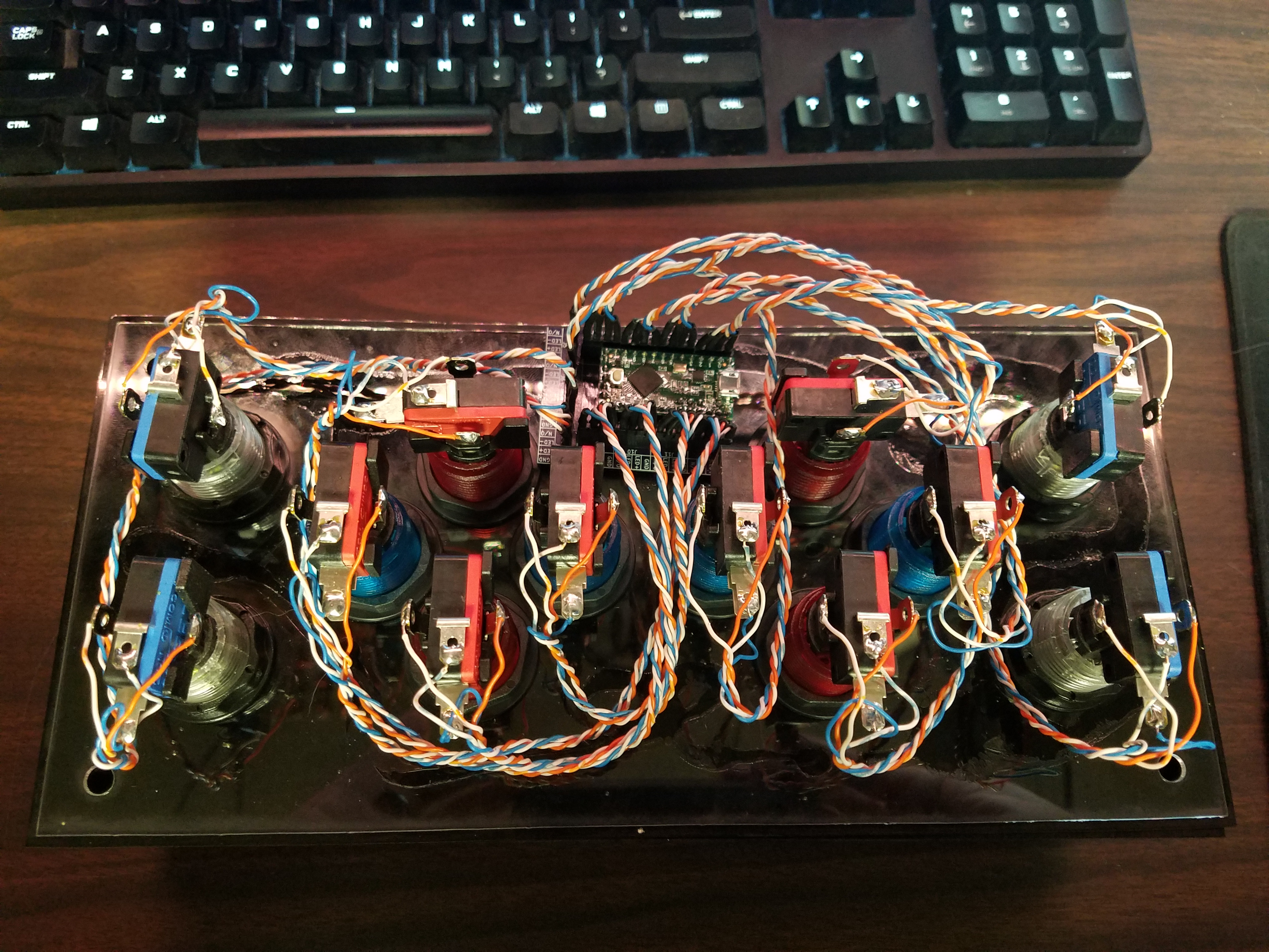
Date Published: 2019-03-22
I recently taught a class about using Teensy as a USB game controller input for your computer Its about an hour and a half of me rambling about how to connect various inputs how to use the Teensy USB libraries and going over example code You can see the entire presentation as a video below and Ive attached the code examples from the github repo here as well for downloadTo get the most out of this class it is best to have a general familiarity with embedded C programming or at least basic programming in general as well as the ability to read basic electronic schematics Heres a guide on schematics from Sparkfun https//learnsparkfuncom/tutorials/howtoreadaschematic/ Hamster ran two classes last year https//wwwyoutubecom/watchvnslHeXYYATM and https//wwwyoutubecom/watchviAMLOtHI that give a good overview of microcontroller firmware which are a good base of background knowledge used in this class The code examples will be written for the Teensy which is built on top of the Arduino IDE The Teensy libraries are all open source available on github https//githubcom/PaulStoffregen/cores so you can modify them for any native USB capable microcontroller of your choice if you are so inclined...
oMIDItone - Part 1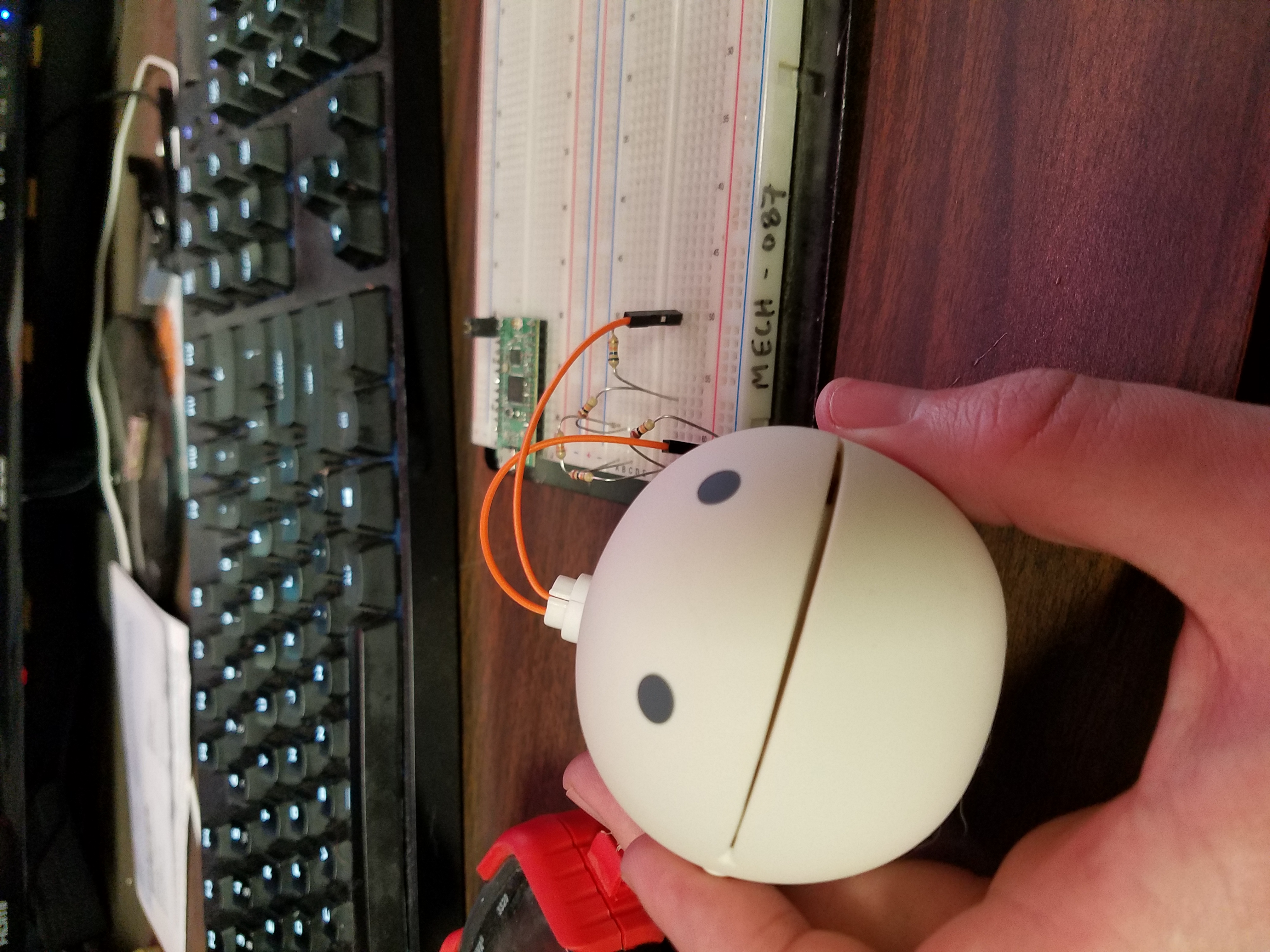
Date Published: 2018-12-20
I recently received an Otamatone as a gift I quickly found out I lack the training to accurately hit notes by ear As a solution to my lack of skill I decided to modify my Otamatone into a MIDIcontrolled instrument This is the story of my first attempt at doing soMy first step was to disassemble the device and figure out how to replace the softpot style potentiometer that controlled the device with a digital potentiometer of my ownThis prooved to be pretty straight forward I used a couple of digital potentiometers I had as well as a solid state relay I had laying around to control when the sound was turned on and off and adjust the resistance to the k value range the original softpot hadIn doing that I was able to control the pitch and get some sounds out of it by sending MIDI commands to a Teensy board See video below for one of the earliest testsOnce I had basic MIDI control I set out to map a resistancetopitch map so I could adjust to a specific resistance and get a specific pitch out reliably It turns out that this was not going to work as I had envisioned Not only were there some anaomolous spikes in output frequency but the pitch mapped to specific resistances seemed to vary wildly depending on unknown variables presumably temperature related but it also seemed to be effected by the last notes played as wellYou can see a graph of the anomolous pitch readings below in the images for the post I tried adding jitter to the resistance and having it randomly oscilate around a resistance but the anomolous pitch changes were still present and never in the same place twice when I ran tests I decided that I would need to do more than just replace the softpot with digital pots I would also need to read the frequency of the output sound and be able to adjust towards a specific frequency on the flyThat led to me adding another two wires tied to the speaker outputs so I could measure the actual output frequency of the sound I was playing Now that this was done I was able to ...
4x4 Keyboard Cases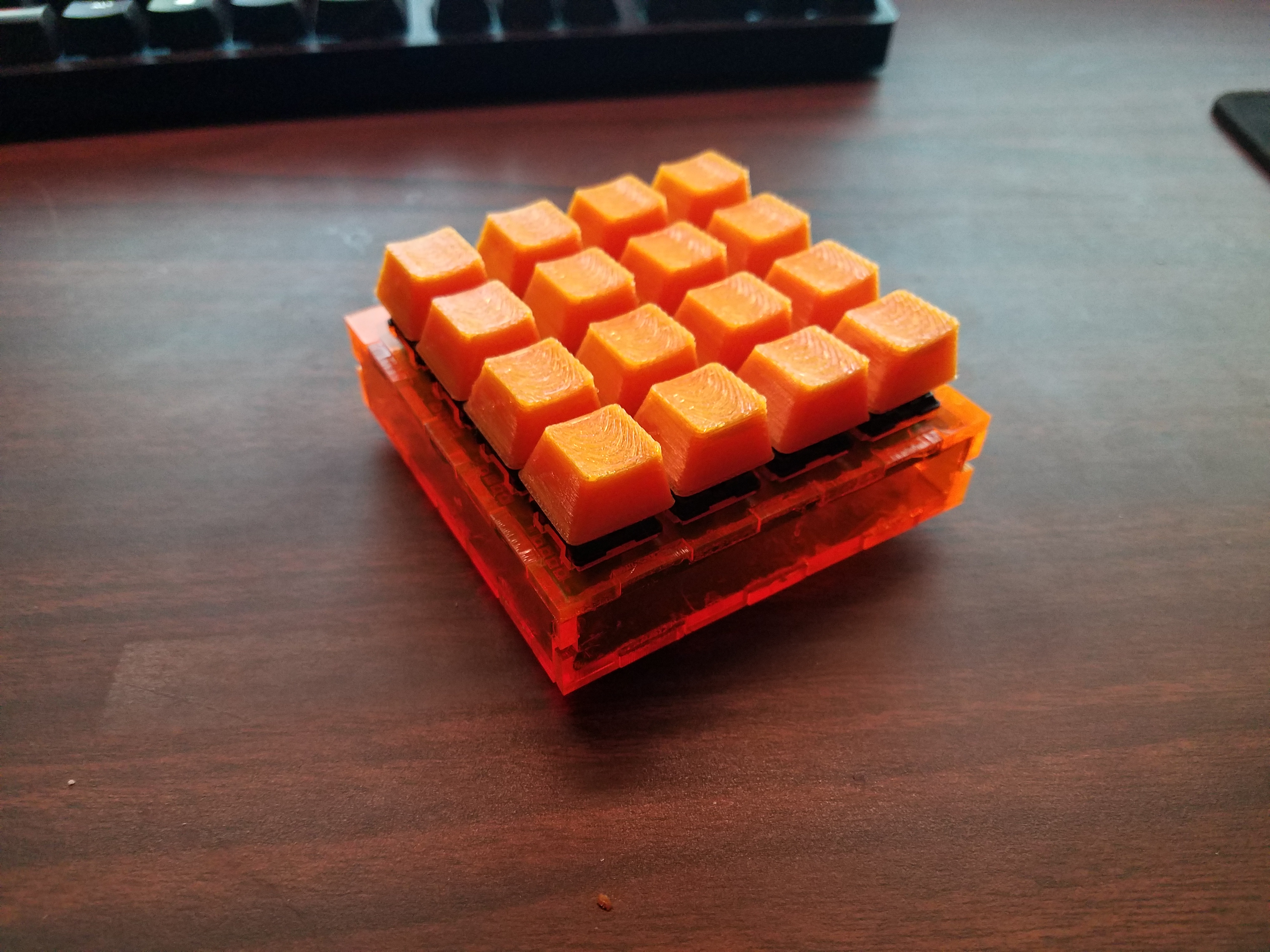
Date Published: 2018-07-09
My friend Marv was selling some x mechanical keyboard kits and I drew up lasercut acrylic cases for them The first case is for the original design which used an arduino micro This turned out to be a difficulttotrackdown MCU and another friend dvdfreitag has made a new version which uses the much more readily available Pro Micro for the MCUMarv posted a build guide for the keyboard There are two case options in each dwg file The first is a simple base plate and key alignment grid designed to be used with standoffs and remain open on the sides The second is a box style case designed to be glued together once everything is working It can also be used with mm standoffs so it can be disassembled for cleaning and maintenance as long as the top is not glued down In both cases the acrylic top plate is used in place of the PCB top plate shown in marvs build guide This is not technically necessary but I think it looks betterThe keyboards run on software generated at kbfirmwarecom and the xjson file below has the configuration for the x boards defaults using a u You can use the site to generate a hex file and then upload it using the qmk toolbox...
LimeSDR Mini Case and FM Filter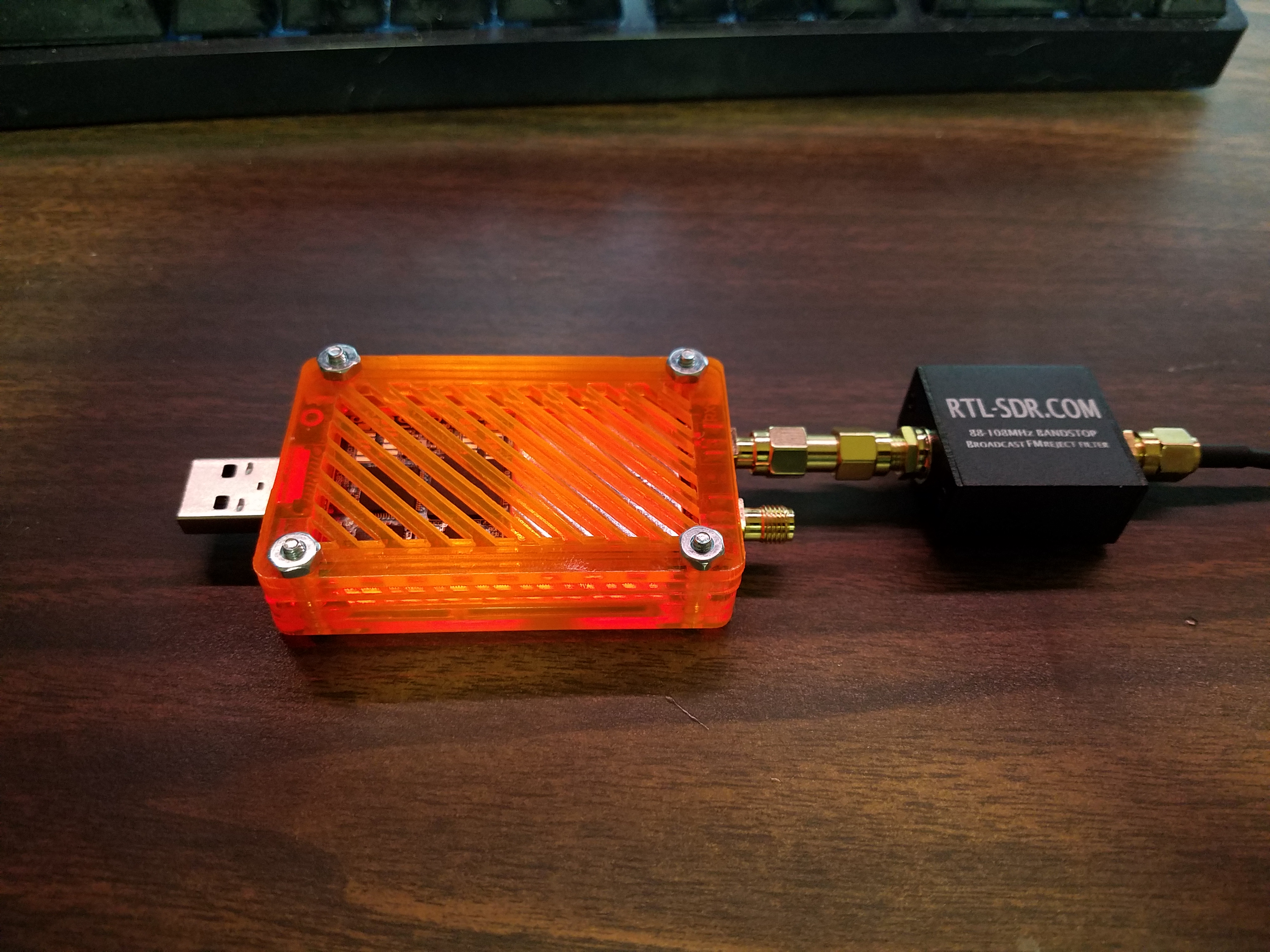
Date Published: 2018-05-30
I made a lasercut acrylic case for my LimeSDR Mini CAD Files below I also installed an FM filter You can see the comparison before and after on the ameteur m band and boy does it make a world of difference.
20m Dipole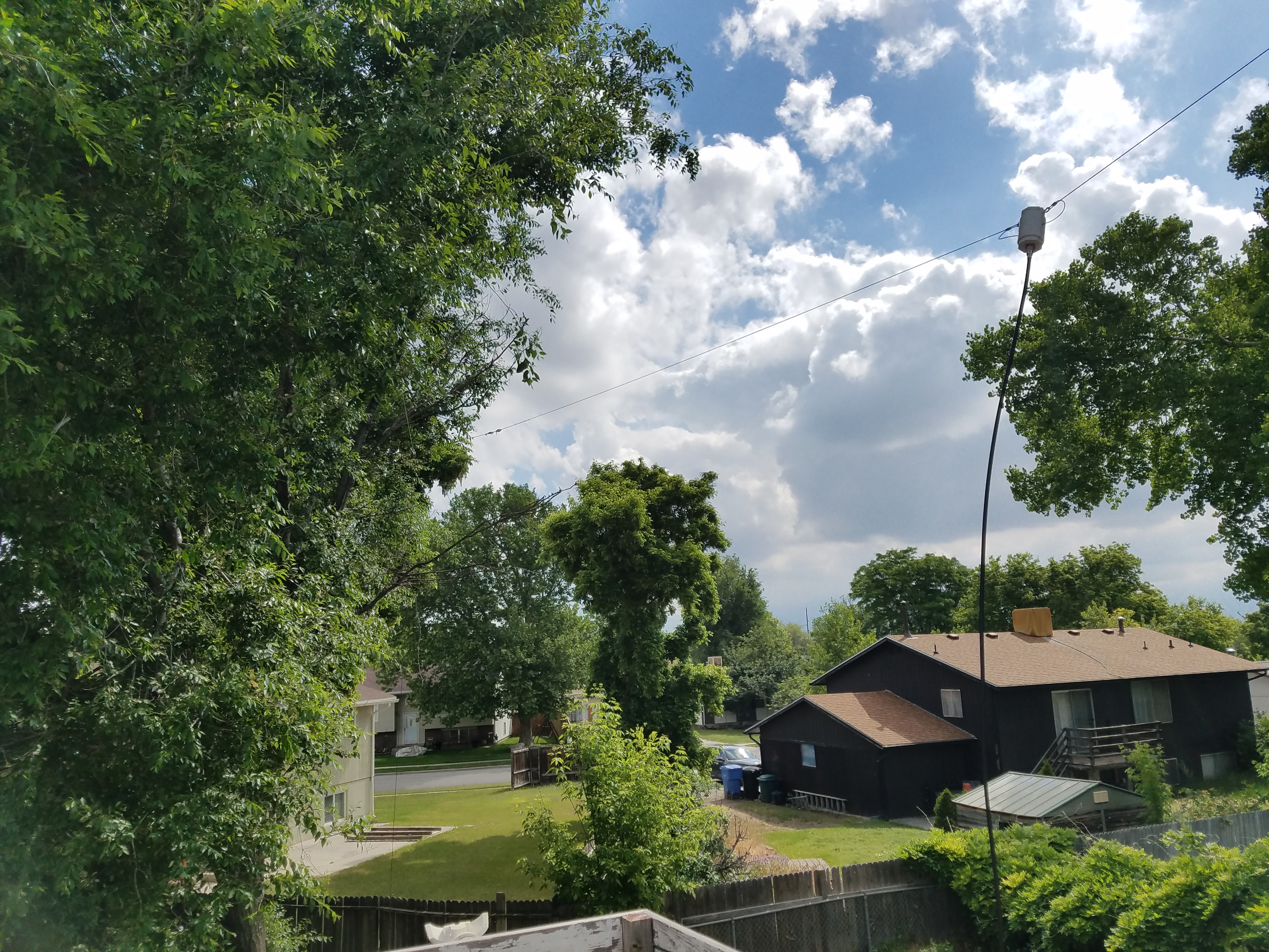
Date Published: 2018-05-28
I just made a very simple m dipole Its two lengths of wire connected to an SO connector in a PVC enclosure and tied off to the swamp cooler on top of my roof and a nearby tree I cut each wire to long initially and folded it back inches to of wire on each leg After testing I folded it back and wrapped it around at the ends to In testing it I get an SWR of to over the m ham band so good enough for me I was curious to see if removing the folded back wire would cause any issues and it caused my center frequency to go up to MHz resulting in a measured SWR of in the m band I soldered the extra length back on and left it wrapped on there to get the tuned chart you see below I am able to hear lots of traffic using my new uBitX as well as my LimeSDR Mini See below for photos of the swr testing and waterfall on the LimeSDR I definitely need to get an fm filter for the LimeSDR as it picks up a ton of FM harmonics in the m band Luckily iirc the uBitX has a filter to block everything above MHz so I shouldnt have this issue on there...
Fake Dynamic DNS
Date Published: 2018-05-28
This is just a simple script I run from my home server to a remote one so I can keep my local ip address updated and remote in with ease I run it every minutes as a cronjob and it generates a timestamped file stating when the ip was last updated as well as a script to let me automatically log in to the most recently recorded ipIt uses https//twaninja/ipphp to generate a string code of the datestamp and ip address Feel free to use my site or make your own similar setup...
IIDX Deck - Build Log - Part 4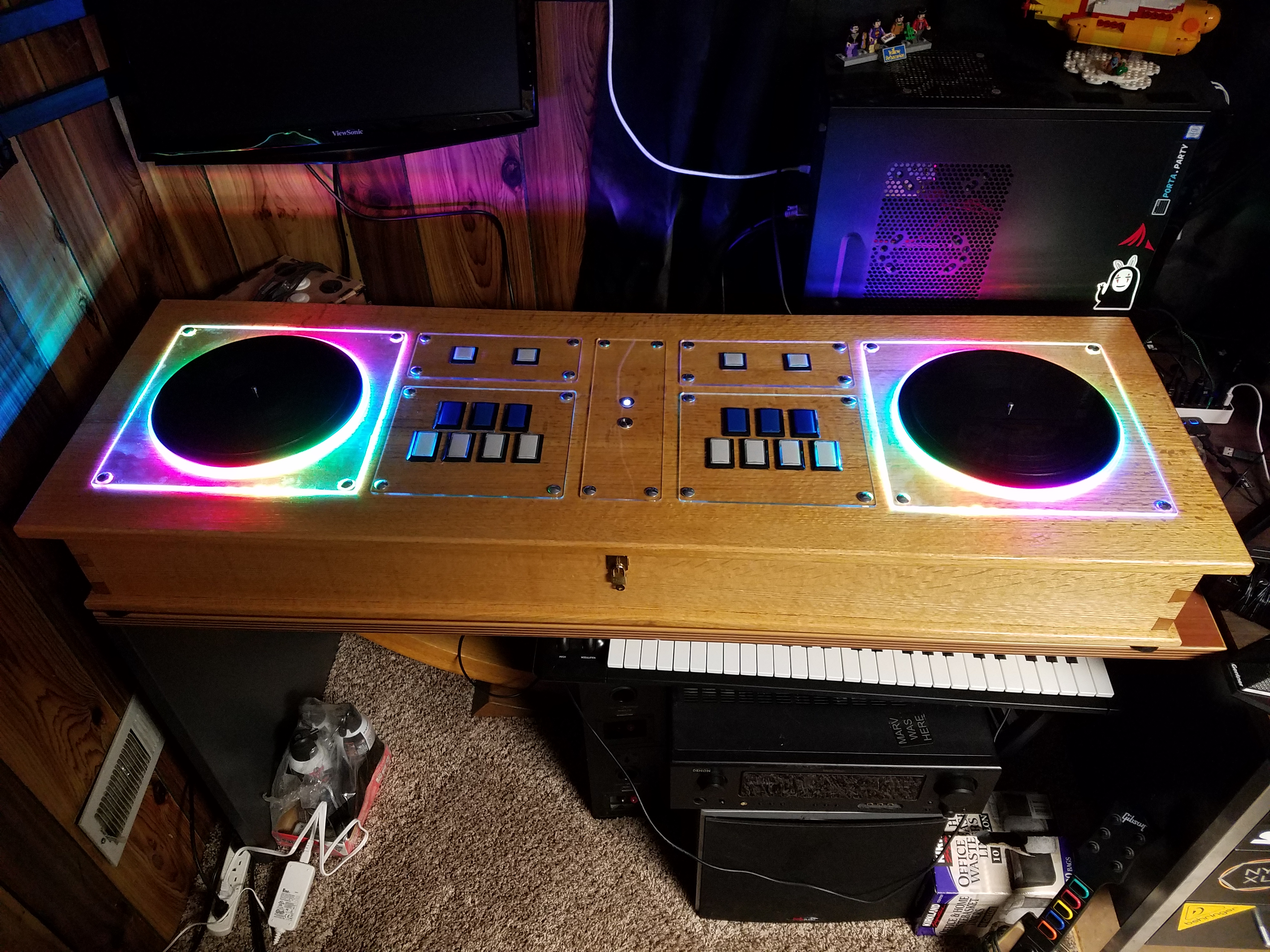
Date Published: 2018-05-28
This part covers the programming and lighting modes Source code is down at the bottom for download as well as on githubWith everything wired up I just had to program basic joystick functionality using the teensy as well as some simple code to read from the digital encoders for the spindles Its all covered in the source code pretty well so I wont get into that too much here What I will cover are the different lighting modes I programmed for the controller Not covered in the source code all the arcade buttons will light up when pressed I did this by routing the LED power through the button The button is grounded when pressed completing the circuit for the LED to light up and open when not pressed preventing current from flowingSome basic thoughts on how the lighting modes function I have a colorsh file which contains several color sets which I refer to as Rainbows in the source code You can swap between rainbows by turning on modifier mode and using the P start and select buttons to cycle through rainbows The rainbows give the various lighting modes below the choices of color to switch to They go from one to the next skipping the off color as needed depending on mode Find below a video showing the various rainbows Most of the videos of particular modes below will use the standard ROYGBIV type rainbow Sorry on the video quality here I have no idea what Im doing with recording bright lights in a dark roomTo change to a lighting mode toggle the MOD button to the on position and press one of the LM keys as shown in this handy diagram R and R will switch rainbows when the MOD key is engaged The Esc button sends an escape keyboard button press when the mod button is engaged so I can exit the program with the controller as needed and the Go button sends Windows Key as that is where I have my shortcut to launch Lunatic Rave in my taskbar If you want to map them to something else its easy to edit in the source code To resume normal play disengage the MOD buttonLighting Mo...
uBitX Enclosure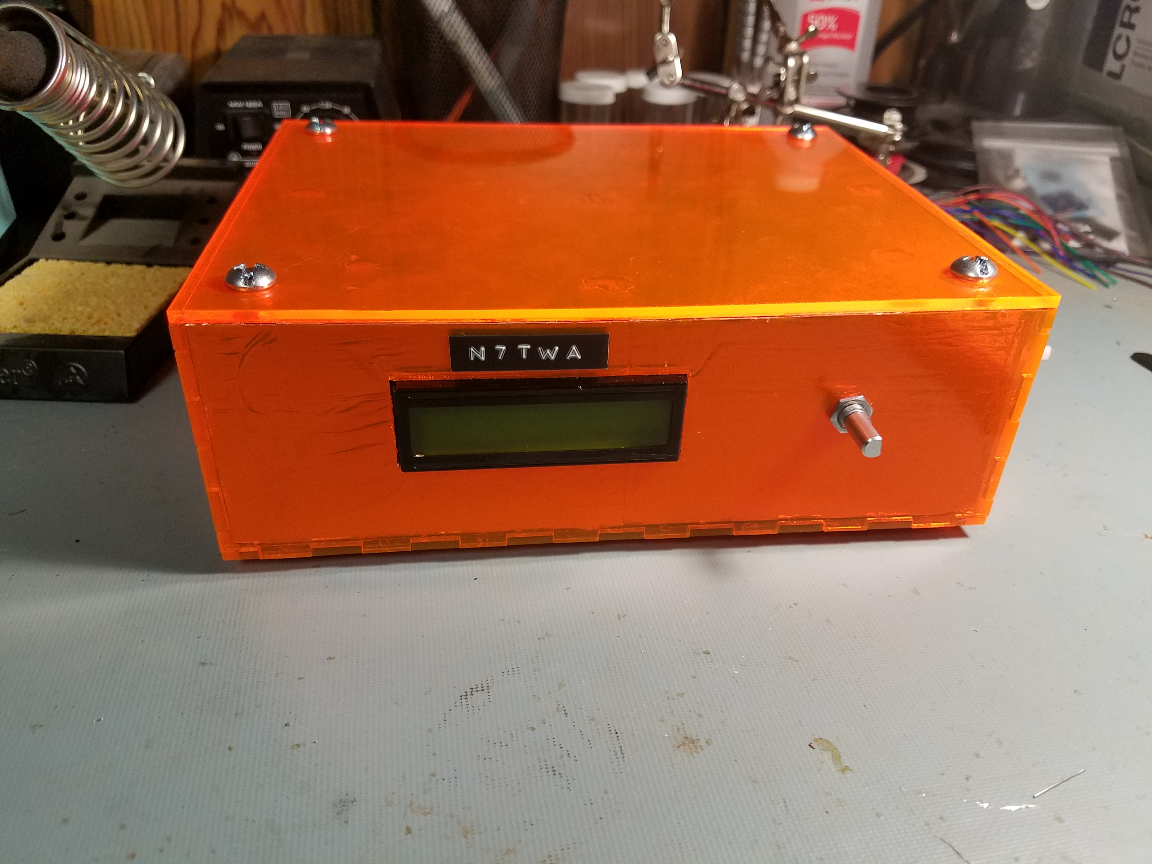
Date Published: 2018-05-19
This is an enclosure I made for the uBitX out of / Acrylic Theres a bunch of pictures of the enclosure and some CAD/pdf files of the enclosure for your use.
IIDX Deck - Build Log - Part 3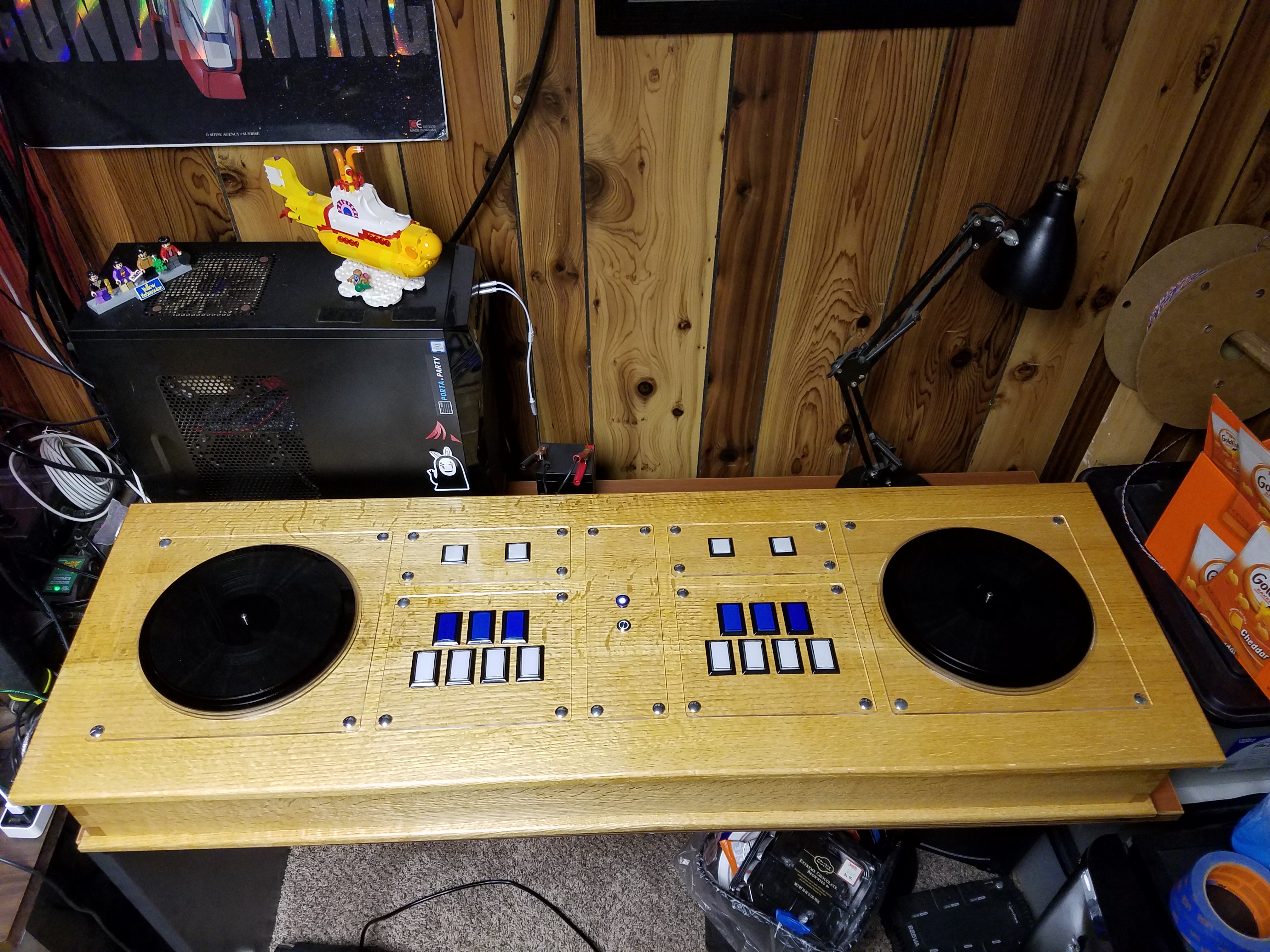
Date Published: 2017-11-12
This part of the build log covers the spindle assembly wiring and initial lighting testingI had originally intended on using an optical encoder attached to a lego wheel I had built a long while ago for the project but it was quite unreliable I figured if I spent this much effort on the project I should make a bombproof spindle assembly for it as wellMy initial design for the spindle turned out to be pretty close to what I actually built Used some bearings and pulleys I paid way too much for on McMasterCarr but writing this several months of gameplay down the line I am glad I went with something a bit overengineered and very reliableI then screwed the spindle assemblies into the top of the deck and added the LED lighting strips The diameter of the circle I chose ended up with LEDs per side A nice large prime number for me to deal with in my animation code More on that in the next partTHe next step was to wire everything up Im using a Teensy as the MCU Ill put the code in the next blog post for download The buttons needed several things connected together so I made some distribution boards for power and multiple connections by hand I also threw in a relay to turn off the lighting power if the USB was unplugged as the controller is powered only over USBI then did some initial lighting and button wiring tests to make sure all was well before I finished wiring everythingI ended up drilling holes for the power cord and USB cable and added some handles on the back to make transport easier as well as a latch on the front to keep the lid from popping open when moving itNow it was all wired Had to fix a couple bad connections but it was ready for programming and lighting business Ill cover the programming and color modes in Part ...
IIDX Deck - Build Log - Part 2
Date Published: 2017-11-01
This part will cover the actual physical build of the deck mostly the woodworking stuffStep was to laminate the oak pieces that would form the topI had also at some point since planing the wood back in laser cut all the plexiglass bits that would form the deck top I laid them out as precisely as I could on the laminated top and then did some drilling and shallow mortisework to get it buttonready This phase took me from into due to life obligations adopting an month old German Shepherd named Ziggy and just not having a ton of time or motivaton to work on itAfter the top was ready I had to make the dovetailed box with panel and frame bottom See below for several pics of this processIt looks more warped than it was in this pic Not sure why I glued up the dovetail section and patched some of the tails as needed...
Radical Dreamers Tab
Date Published: 2017-01-15
I wanted to learn to play the song Radical Dreamers composed by Yasunori Mitsuda for the Chrono Cross soundtrack I found some piano sheet music online and made a guitar tab based on it Hopefully someone out there will enjoy it as well.
IIDX Deck - Build Log - Part 1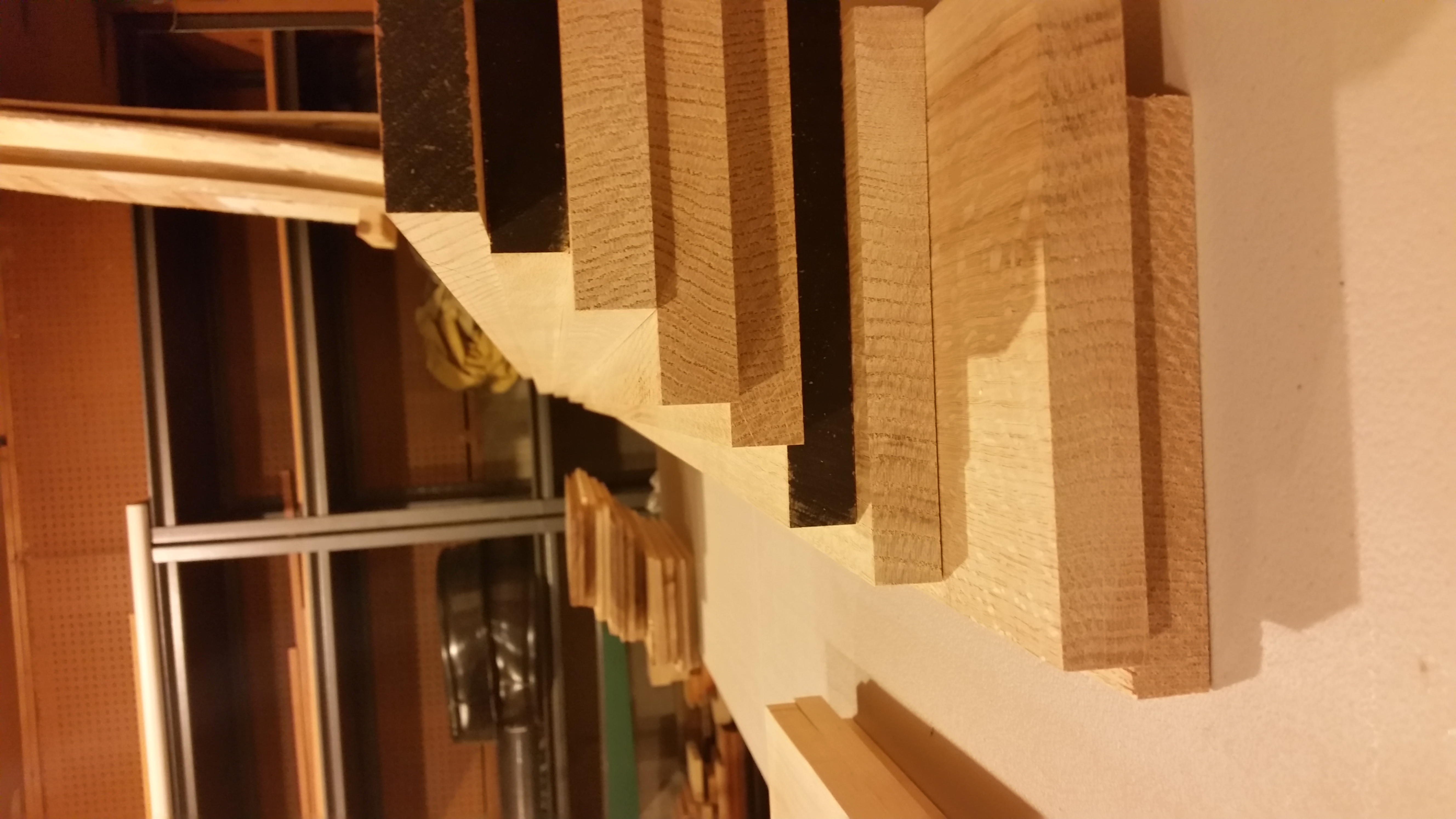
Date Published: 2015-09-18
This covers the initial design and failed attempts way back in and eventually starting over in So this is a project I started back in at HackSLC predating even the Transistor I wanted to build my own Beatmania IIDX arcadespec controller When the project first began the idea was to dismantle the american PS controller I had and give it some better buttons and a wheel so I could still use it for my American PS version of BeatmaniaThese first two pics are of my trying along this path back at tT in Provo Not a lot of records form that time One shows the unmodified IIDX america controller and the other shows my first attempt at a disk It spun well but I never got the hall effect sensor and magnet array inside to work rightWe can now skip forward a few years to I was midburnout phase from after Elefu much more into woodworking than electronics and decided to revisit the controller project I came up with a totally new design based around the new woodworking skills I had acquired and the laser cutter for cutting the deck I was going to go allinI made a sketchup file for my design download at the bottom based on these dimensions for the arcade controller I found onlineWith that out of the way I set to work on the woodworking I planed a bunch of oak first and left it to sit for a long while in my shop before beginning work in earnest...
Wedding Arch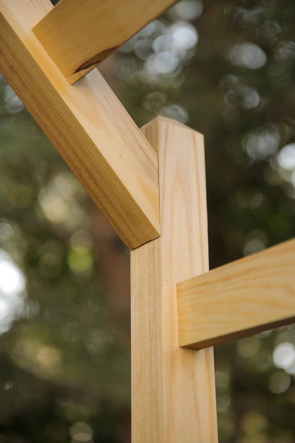
Date Published: 2015-09-12
This is a bunch of photos of the build for the arch for my wedding Its done with a ton of mortise and tenon joints and glue The top bars are at a degree angle the rest are all square joints Made from cedar and finished with linseed oil.
Planer Cart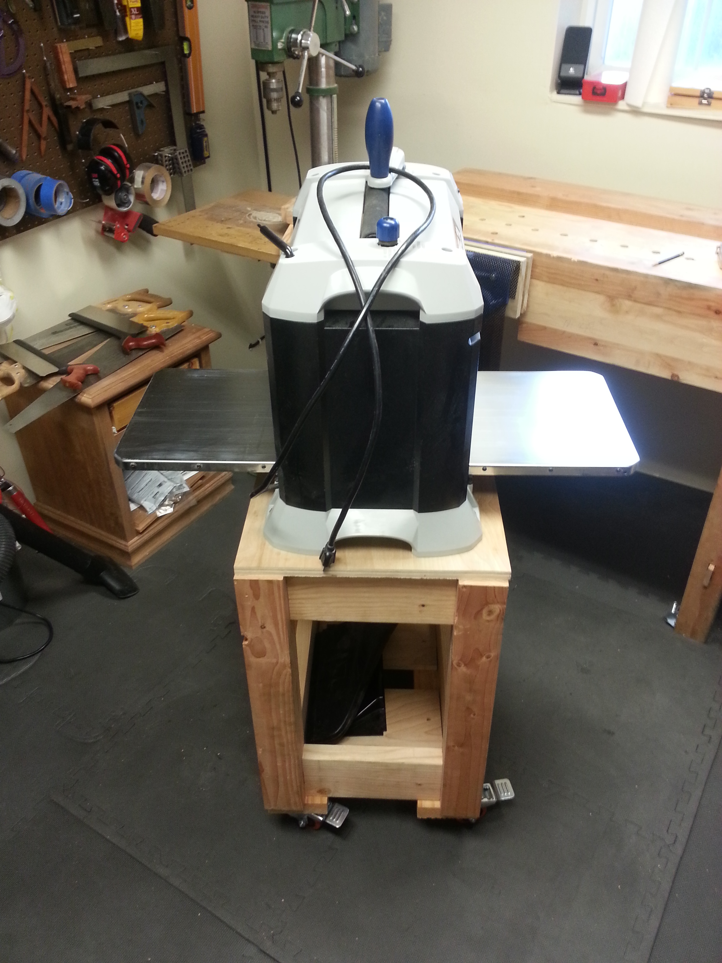
Date Published: 2015-07-23
I got a practically free planer so I decided to make a stand for it x and x Pine and Plywood with Mortise and Tenons and Screws.
Dovetail Utensil Box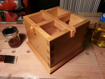
Date Published: 2013-12-03
This is a dovetail box that I made for the purpose of holding utensils in my kitchen such as large spoons ladles spatulas and the like It was also to practice making handcut dovetails and finishing The dovetails were all made with nothing more than a saw and chisels and a marking template I made as my first attempt at woodworking a few months back I also made a tiny square to check them for square as I went Its not perfect and I have some gaps and splitting on a couple of the joints but all in all Im happy with how it turned out as my first real project real in this case meaning not a tool to be used to make other projectsThe cross beams are just halflapped together with square notches cut into the sides for them to rest in again with a saw and chisels Its all held together by wood glue and only wood glue The bottom was actually made from two boards that I jointed by hand and glued together then I glued the whole thing to the sides Im not too worried about wood expansion as its only long but hopefully it doesnt pop off at some point down the road If it does I could always dowel it into the base and hope thatd hold betterI finished it with two coats of shellac that I mixed myself from flakes It seems to have worked out well despite a couple bumps I still need to sand off This is also my first attempt at finishing a project Sorry for the lack of progress photos I didnt have my phone on me while I was making most of this project Ill try to keep a better log on the next one Lots of learning going on Next stop breadboard ended cutting board town...
Phase Shift Guitar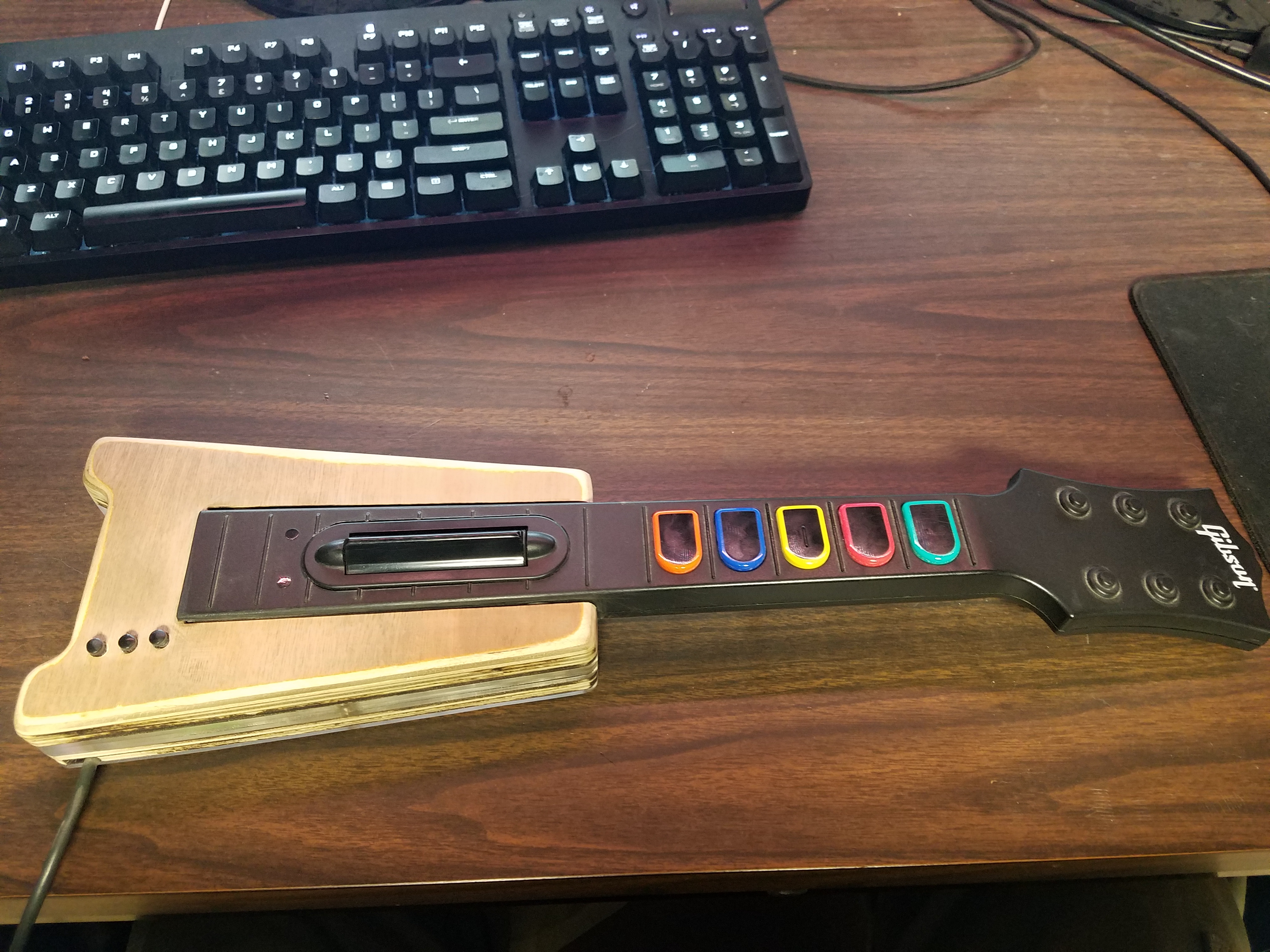
Date Published: 2013-06-12
Back in I made a small guitar for playing Phase Shift by cannibalizing a Wii Guitar Hero controller It runs on an Atmega u and is housed in laser cut plywood and acrylic and contains some poorly utilized Addressable LEDsSee below for pictures and the CAD file for the acrylic and Plywood cutouts files as well as the source code thats currently running on it This is a project I definitely want to revisit by swapping out the u for a Teensy LC adding many more addressable LEDs and applying some of the knowledge of my IIDX deck lighting to this old project as my skill with Addressable LED animation has grown substantially since I made this little guitar Ill probably also replace the sad unfinished plywood with some nice hardwood Look forward to an update or two in the future as I rework this one...
Stepmania Controller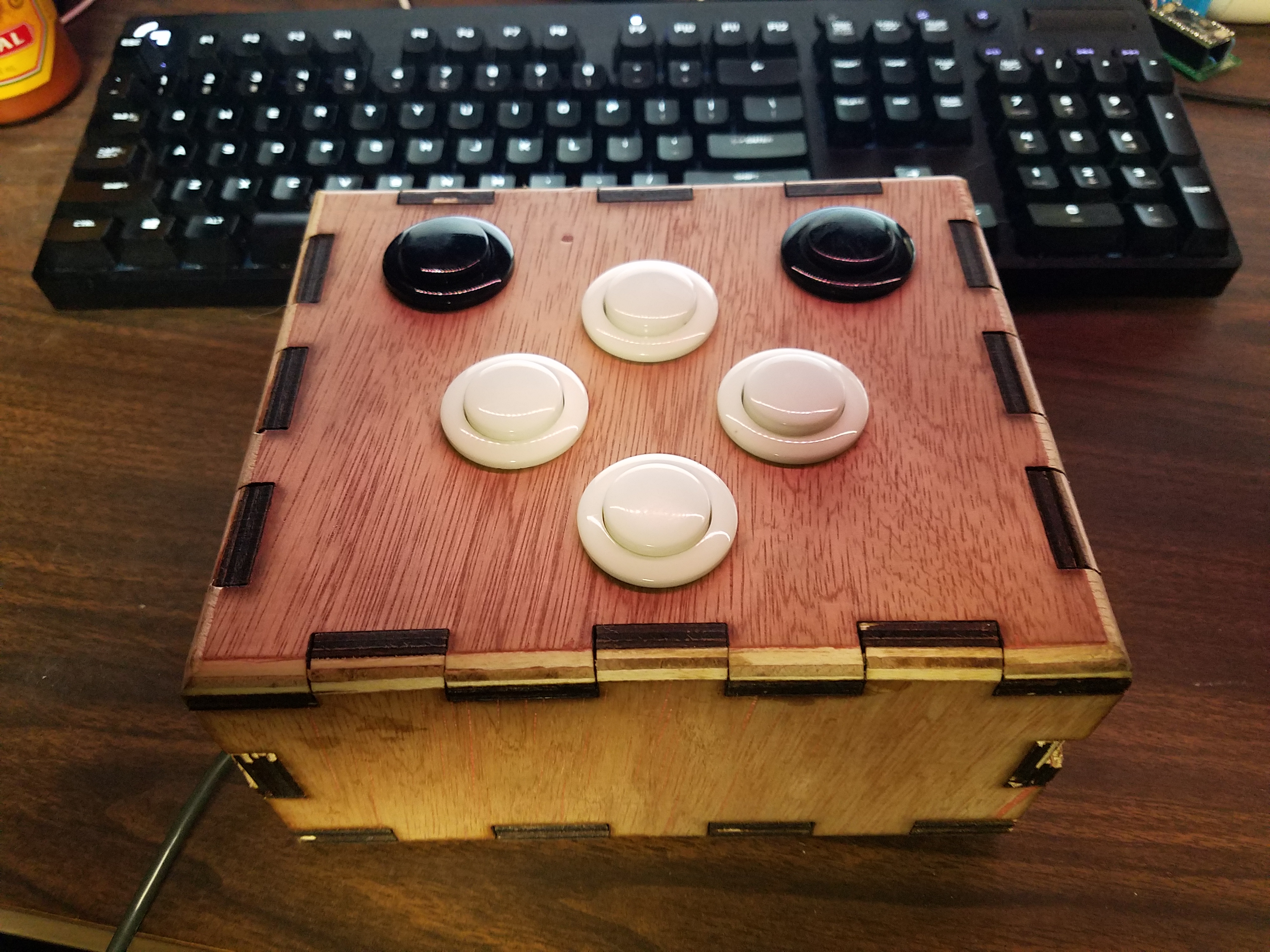
Date Published: 2013-05-25
This was a simple arcade controller I made with the laser cutter an Atmega u board and some arcade buttons Another simple project It worked pretty well for quite some time but I just plugged it into my Windows computer and I got a lovely BSOD so I might want to revisit this one in the near futureI know Id go for a Teensy LC if I made another one of these and maybe give it the IIDX treatment with nice lighting modes See below for some pics and my CAD file from the laser cutter.
Moving tT from Provo to Orem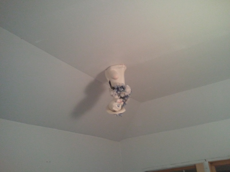
Date Published: 2012-11-30
In late we moved the Transistor from Provo to Orem This has made a lot of people very angry and been widely regarded as a bad move Here are some pictures from this time including of the weird cat statue we glued to the ceiling before we left.
LED Cube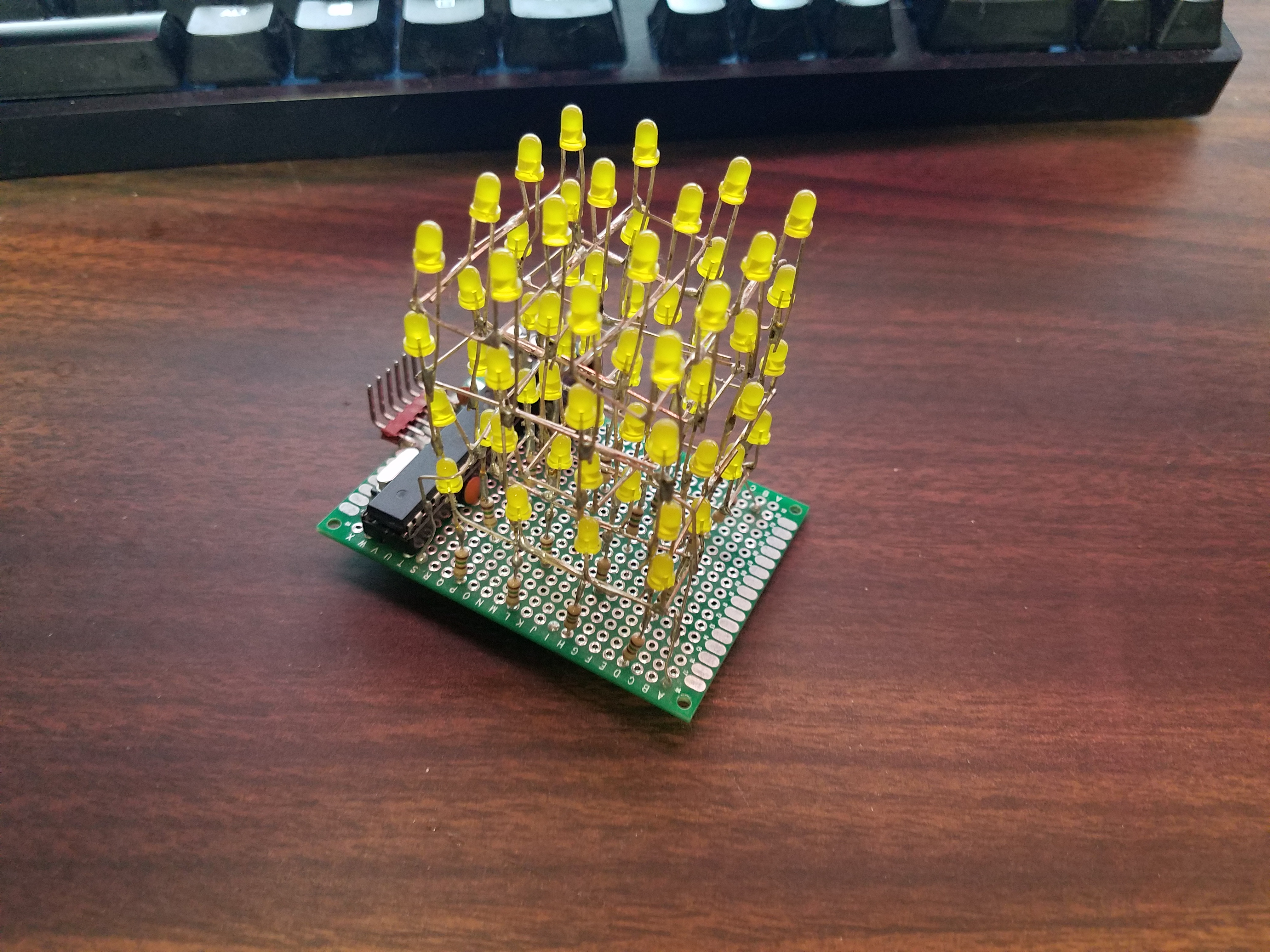
Date Published: 2011-11-01
This is an LED cube I made from a minimalist arduino some resistors and a bunch of LEDs back in Not much to it really and a couple of the LEDs are out at the moment Not sure why shrug.
4-Player MAME Cabinet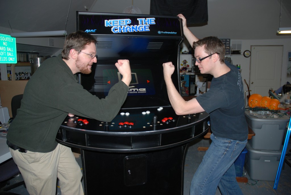
Date Published: 2011-01-15
This is a post for the player arcade cabinet dcf and I made back around dcf did most of the general idea work and I did all the CAD work I believe these CAD files have been updated with added tolerances but double check if you want someone to cut them for you Our first batch was a bit too thin on the routed channels and we had to manually route the edges off of everything to get it to fit No warranty is implied or included etcIt was designed to work with any VESA mount monitor and as far as software/hardware youre more or less on your own I recommend a Raspberry Pi running RetroPie and the joysticks and buttons of your choice Theres a parts list in the file download area below for reference No idea is any of the bits are still available as listed.
Zombie Laser Tag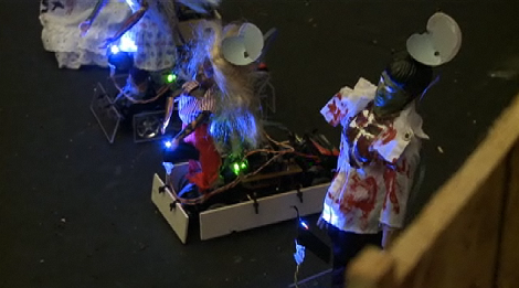
Date Published: 2010-11-05
This game was made as part of an internet video series back in late It was called the Take on the Machine Challenge and pitted hackerspaces against each other to make a cool project given a donation The Transistor decided to make a zombine laser tag game using RC Cars Gorduinos and XBees Unfortunately the video documentary of our work has since been taken down and we dont have a ton of records from this time I did find a bunch of photos from the build though and some code from the zombie bots and the laser guns we made so I will share those on here for everyone to see.
Gorduino - Original Blog Recreated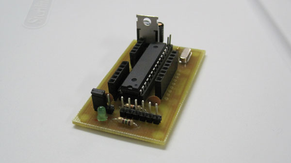
Date Published: 2010-08-22
This is another recreated blog post from thetransistorcom Gordo actually did all the work on this one but I wanted to preserve this piece of tT history on my own blog for the futureProject OverviewThe Gorduino is a PCB board layout designed to work with our Minimalist Arduino Kits It was designed by Gordon Cooper with input from other Transistor Members Features include Access to all Arduino pins DD and AA Ground Pins adjacent to all Digital Pins V Rail and Ground Rail adjacent to all Analog Pins for ease of sensor use USB/External Power Selector Jumper Pin Single sided board for easy home reproduction Small form factor compared to typical Arduino footprintEagle Schematic FilesFiles for va Current Version See download links belowChanges from va Added V rail on analog pins General cleanup and trace size/position changesFiles for va Zombie Defense Version See download links below...
The Night We Flooded tT Provo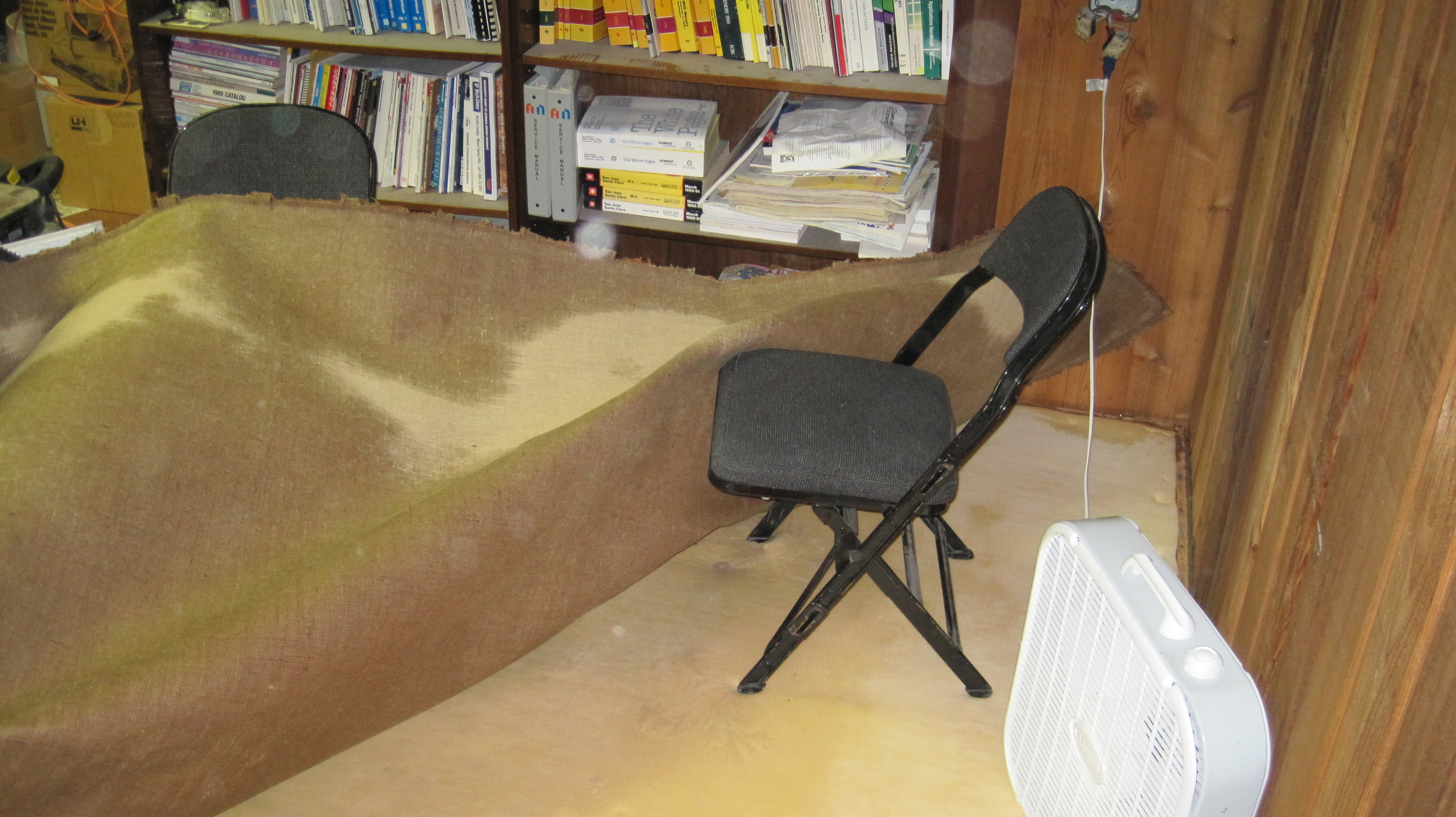
Date Published: 2010-08-18
On July we installed a shiny new counter and sink in the attic of the Startup Building in Provo where the Transistor was located Good times were had by all until Tuesday August Around PM I received a call drom dcf who informed me that apparently the whole building was flooding and the source was the sink we had installed and used happily for almost a month I resigned myself to the chaos that was to ensue and headed south from my apartment in West Jordan We ended up spending most of the night pulling up soggy carpet removing wet ceiling tiles which likely contained asbestos and pulling sopping wet batt insulation from the ceilings until around in the morningThe water had come from a compression fitting on the water supply line that had popped open It made it from our spot in the attic all the way down to the showroom floors belowWe did eventually get everything cleaned up and dry replaced the ceiling tiles and insulation and made damn sure the compression fittings on the sink were not going to come loose ever again On the plus side we did discover a startup from the late s that was focused on something similar to modern day RAID arrays called Dune They had aparently been paying rent since and had not visited their office once in that timeframe just left all their stuff there...
Nixie Clock - Original Blog Recreated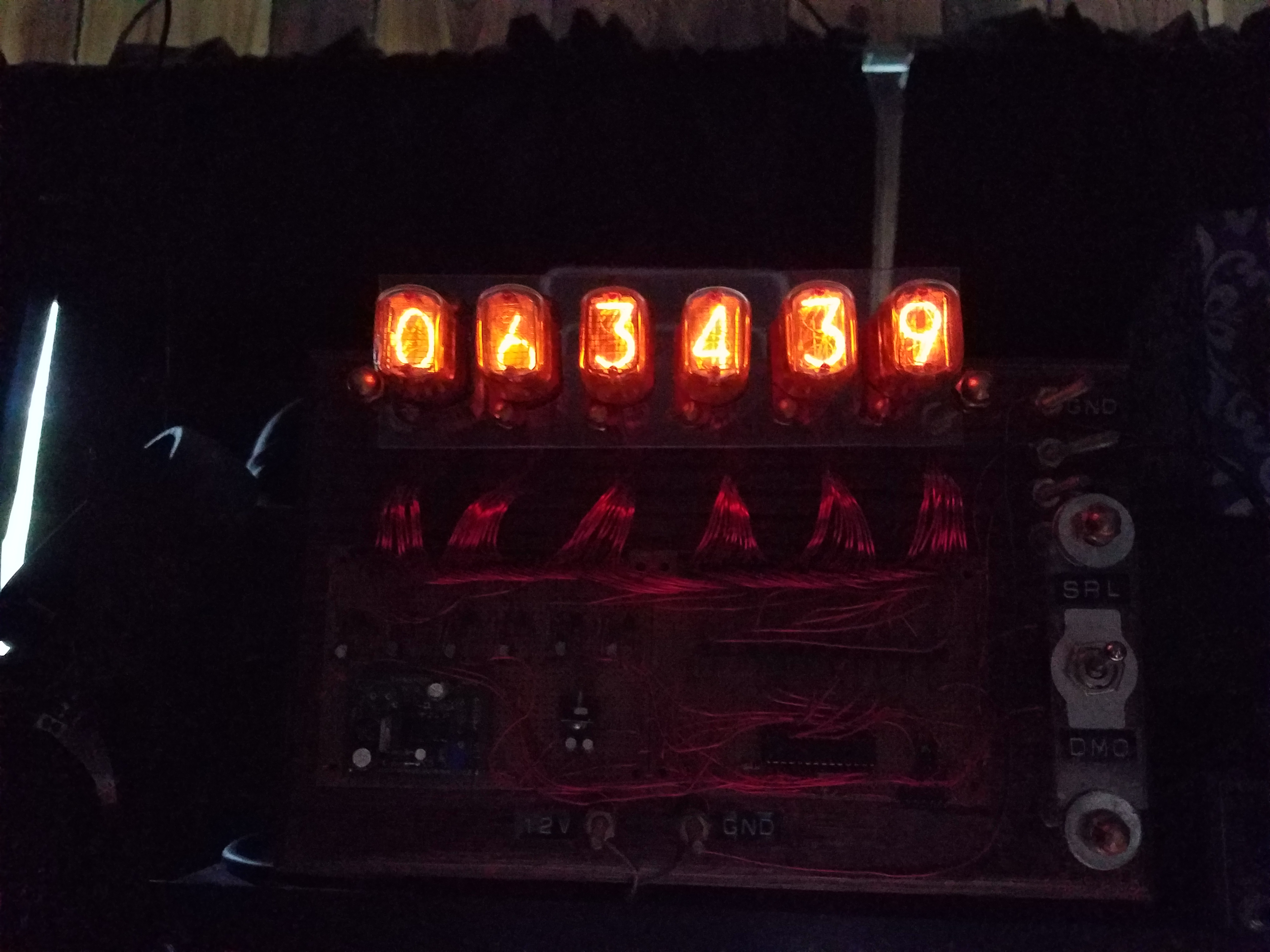
Date Published: 2010-05-12
Below you will find the mostly preserved original build log for my Nixie Clock formerly posted on thetransistorcom circa Ive also included my original schematics for download Ive also included some comments in parantheses from presentday meHello everyone Ive designed and built myself a Nixie Tube display and Im now going to impart upon the world my build log schematics PDF and Arduino source code If you have any questions or comments you can email me at tim at thetransistor dot com Yeah my email is now tim at thisdomain these days Also the schematics and code will be downloadable at the bottom of this pageProject Overview The goal of this project was to create a nixie tube display using one of our Minimalist Arduino kits and some nixie tubes I happened to come across It has a demo mode to test the tubes and it also accepts serial inputs to set the display In the future I intend to add a second module which will have an atomic clock receiver and use it as a wallclock at my apartment but thats another story for another page Heres a video showing the finished product in all its gloryAnd heres a video with me breifly explaining itNo beard Gods I was young back thenBuild LogIt all began with me receiving a pile of nixie tubes abandoned at the Transistor I resigned myself to figure out how to make a controller and eventually a clock for themAfter doing a bit of research I bought a DCDC High Voltage Converter from the good folks at All Spectrum Electronics http//wwwallspectrumcom/ The exact PSU I used is no longer available Look for something that will take in V and output V DCI then ran some tests on a tube to see if I could control it with an arduino and transistors as shown in the schematics above Heres a video result of that testYou can see that PWM control of the tubes is possible and could lead to some nifty transition effects later if I stop being so lazy about writing code for it Anyways with confirmation that the tubes worked with the power supply and Arduino ...
Animatronic R2-D2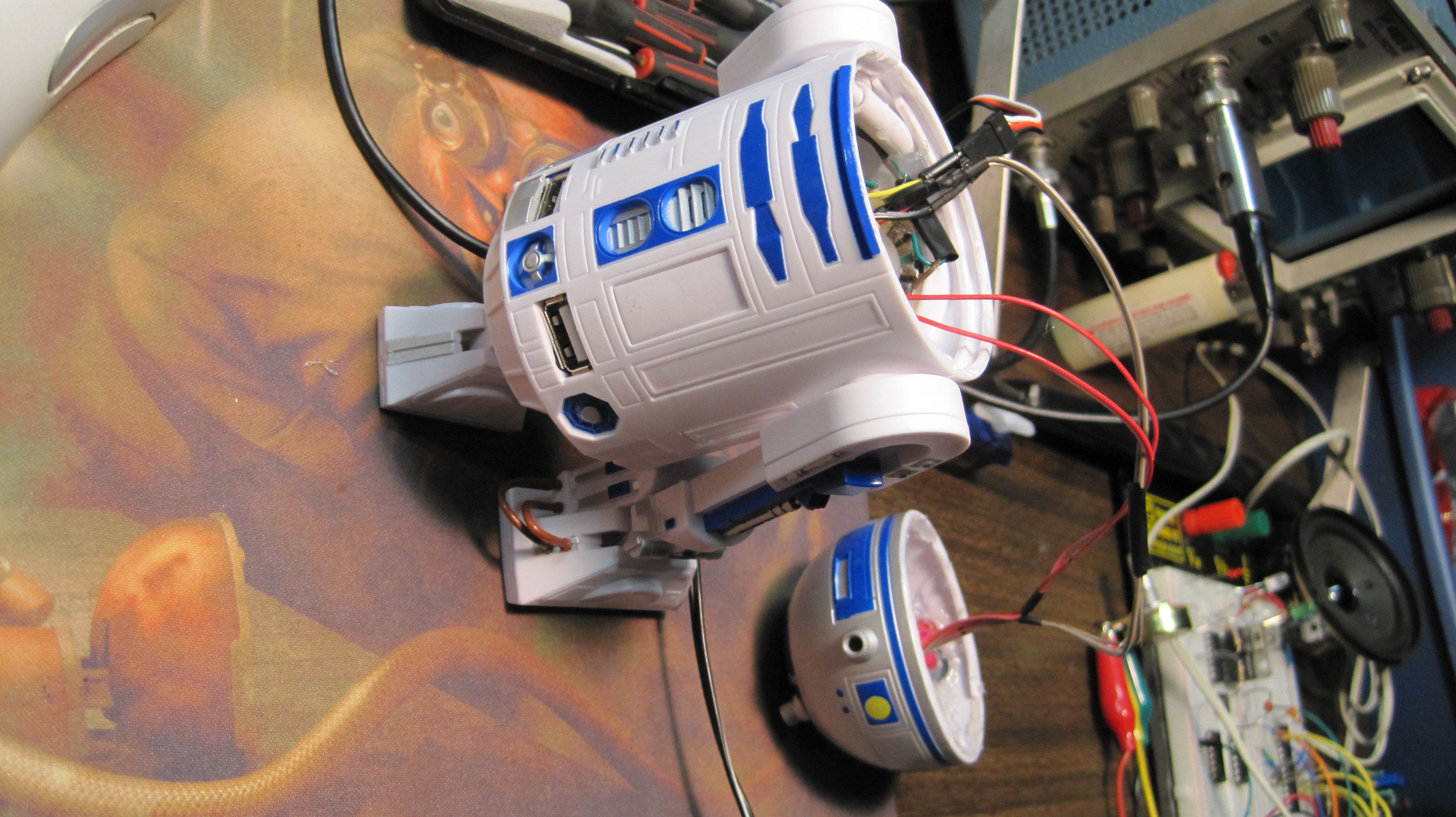
Date Published: 2010-04-02
This is a project from the old Transistor days It never got a blog post but it should have so now it will My Friend Wharff had an RD USB hub that made a long series of beeps when a button was pressed He wanted to learn about electronics and asked for my help in making the top of Rs head to move about with blinking LEDs when the button was pressed in addition to the sound it makesIt ended up taking several weeks through much stress and learning We made a minimalist arduino to leave in the body of R and fashioned a way to get a red LED as well as a white one into the head and shine through his hologram projector port We got it to randomly move to various positions for the duration of the second long sound clip and then return to center and project a hgologram when done by blinking the white LED at varying intensity There was a fair bit of frustration in this build but it ended up working and allowed me to get to know one of my now closest friendsI just took it off a shelf dusted it off and filmed this video of it still working today.
Minimalist Arduino - Original Blog Recreated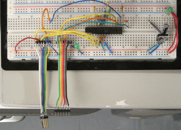
Date Published: 2010-02-02
This is another blog post from the early tT days I wanted to preserve for posterity We were selling kits of the bareminimum components to make an arduino board Im leaving all the links in this one to the wayback machine because Im lazy Even without the links working you ought to be able to make one of these given the fairly generic parts listOverviewHere at the Transistor we love the Arduino platform so we decided to make our own Arduino Clone The Minimalist Arduino is designed for use in permanent or custom circuits on solderless breadboards stripboard or custom PCBs It contains only the bare minimum parts required for building the Arduino platform The schematic for the board can be downloaded here pdf Please read all instructions on this page before assembly The parts list is as follows with linked manufacturer datasheets when availableParts List ATMegaP Pin DIP Socket LM A V Positive Voltage Regulator MHz Clock Crystal pF Capacitor uF Capacitor nF Capacitor kOhm Resistor Ohm Resistor Green mm LEDThese parts consist of two main components The power supply circuit and the ATMegaP and supporting circuitry The power supply circuit is made of of the LM voltage regulator uF capacitors Ohm resistor and green mm LED Circuit power can be supplied using these components and a to V input voltage or via a separate regulated voltage source such as power over a USB to Serial FTDI converter Only use one power source to drive the P chip or you may damage itThe remainder of the components are part of the ATMegaP circuit and support This includes clock crystal pF capacitors kOhm resistor mm Green LED Ohm Resistor and nF capacitor The kit contains no wires jumpers or reset switch as the applications of this kit are intended to be openended and we did not wish to include unnecessary componentsCommunicating with the Minimalist ArduinoIn order for this kit to be fully functional you must have a means by which to program and communicate with it We did not...
