oMIDItone - Part 2
Date Published: 2019-05-10
When last we visited the oMIDItone project, the plan was to turn the test code into a class, and add more heads to allow for a wider range of pitches to be played at once. Sounds simple enough, but it took a lot longer than I ever thought it would, with many complications and lessons along the way. I'll go over everything in roughly the order it happened in, starting with code challenges, then moving on to hardware challenges, and finally the (more or less) working prototype. Hold on to your hats, as this post is almost as long as it took me to build the damn thing.
Code:
Turning the code into a class turned out to be fairly straightforward, but did lead to some issues I didn't have with just one head. The first issue was that when storing an array of 32-bit microsecond note frequency values for every head, the Teensy LC's RAM is not large enough to run all 6 heads like I had planned. This would eventually necessitate the upgrade to a Teensy 3.2, but I didn't figure that out until after I had made a terrible PCB for the Teensy LC to run the 6-head design I was planning. More on that in the hardware section.
Once the memory issues were out of the way and I could test with more than one head, it became apparent that I was having additional problems with using the original code as-is. What worked fine with one head running broke down with more than 3, especially at higher frequencies. The problem ended up being that my analog sampling using the default library was not fast enough. I found this awesome library online, and was able to get the sampling rate up high enough to read all 6 heads at once without issue. This was done by lowering the sampling resolution to 8 bits from 12, and using the fastest settings the library offered.
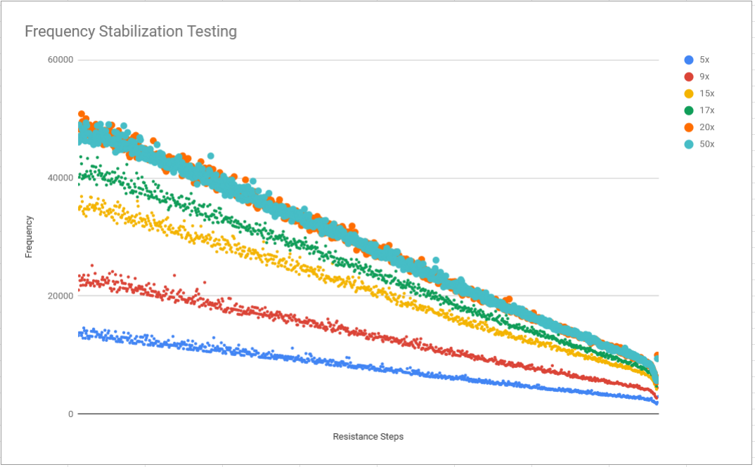
With the ADC sampling adequately, I was finally able to get all 6 heads to operate more or less properly at once. It was then that I noticed that the frequency sweep testing I was doing on boot wasn't accurately getting the final frequencies the notes would play at. This caused me no end of trouble, and I am just now getting it worked out properly at the time I am writing this blog post. Long story short, the frequency will take approximately 100 cycles to reach a stable tone for a given resistance, and I was measuring at somewhere between 5-10, which resulted in the notes skewing to a higher frequency than they should have been. You can see in the chart below labeled 'frequency stabilization testing' the testing that shows the steady lowering of frequency (more microseconds) as the number of cycles before testing increased. As I increased the number of cycles, the frequency would lower, until it finally stabilized around 20 tests (at 5 samples each, this adds up to 100 iterations), and after that it stopped varying as much.
Now that all these issues were resolved, and the notes were playing correctly as soon as the startup_test() function was complete, I tackled deciding which MIDI notes to play. I settled on keeping track of when the MIDI notes were received, and checking the heads every time a note changed, then playing the most recently received notes first, and the oldest notes last. This final touch has made it so that the oMIDItone can actually play recognizable music straight from MIDI files. Depending on the file, it even sounds pretty good.
Hardware:
The hardware design for the oMIDItone has been quite the ordeal, and was riddled with uninformed decisions, and what should have been easily avoided mistakes. I'll pick up where I left off on the last post with the initial transition from a hand-soldered test board that could run a single head, to my initial PCB design for the 6-headed board. I will not be publishing the original 6-head board design, because it is flawed in so many ways I would feel bad putting it on the internet. I will be making a new control board incorporating all the things I have learned throughout the project up to this point, and when that is done I will post it as part 3 of this series.
The first mistake I made on the oMIDItone control board was designing it for a Teensy LC instead of the 3.2 I would eventually need to use. This required me to do some pin jumping to get all the pins I needed available to the right locations, as even though the LC and 3.2 share most pin positions, there are still a few that don't line up, and I was already using all the LC pins for the first PCB design.
The second mistake I made on the oMIDItone control board was to number the pins on the MCP4151 digital potentiometers I used incorrectly in Ki-CAD, which resulted in half of the pins being connected in reverse on the PCB I ordered. After a few tries at using 'spider chips' with long wires soldered to the pins of a DIP-8 package and flipped to plug into the board, I eventually had to design a replacement PCB that would flip the pins for me.
The third problem with the board wasn't so much a mistake, as it was using something I had that was very much overkill for the intended purpose. I happened to have some large solid state relays around rated for 20A each, and I used them to control the ~130mA max current flow through the digital pots. This decision was made primarily because I had them on hand, but also because I had not yet taken the time to figure out exactly what the circuit inside an otamatone was doing, and I figured the SSRs would work regardless of the original circuiting. The end result was that the board was very bulky, and overdesigned with six $8-ish parts when it could have been made with a few <$1 optoisolator chips instead.
All of the above are the reasons why my first 6-head oMIDItone PCB is a bit of a disaster, and before I could even start testing the new code I had to deal with all of these issues. Once that was out of the way, I bought several new heads and hijacked the resistor and speaker pins and fed them back to the board. With this basic setup, I was able to get all the heads to play some sounds, and things seemed like they were heading towards functionality after all this time and fixing my bad hardware design decisions.
After about 4 hours of testing and messing with the code, things started getting weird, and it turns out that the batteries in the otamatones were dying. I then realized that every time I used this thing, I was going to need to feed it twenty-four AAA batteries. That obviously wasn't sustainable, so I had to find a way to power the heads from a single source. This would require once again disassembling and rewiring a bunch of things to get it all to work.
During the part of the project where I was tracking down where to connect batteries and testing power supplies, I discovered a couple important things about the otamatone circuit I had overlooked in my initial hardware design.
- The first was that between two of the batteries there was a thermal fuse that runs at ~1.5 Ohms until heated, when it will increase in resistance to prevent blowing out the transistors on the otamatone PCBs. I discovered this by bypassing the fuse unwittingly and blowing out a transistor on an otamatone PCB.
- The second was that my power supply replacements (both battery and wall-transformers) were not able to maintain their voltage while running more than one head. This caused what I now understand to be a 'crosstalk' isue where other heads would chatter when, presumably, the voltage on the power supply was dropping altering the timing circuits on the other heads. I solved this problem by using a few 1000uF capacitiors to stabilize the supply. Though at the time it sounded like my alternative power supplies were overdriving the speaker causing it to crackle, so I spent a good deal of effort troubleshooting the wrong problem before I got to this solution.
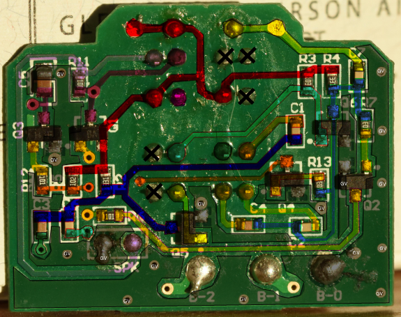
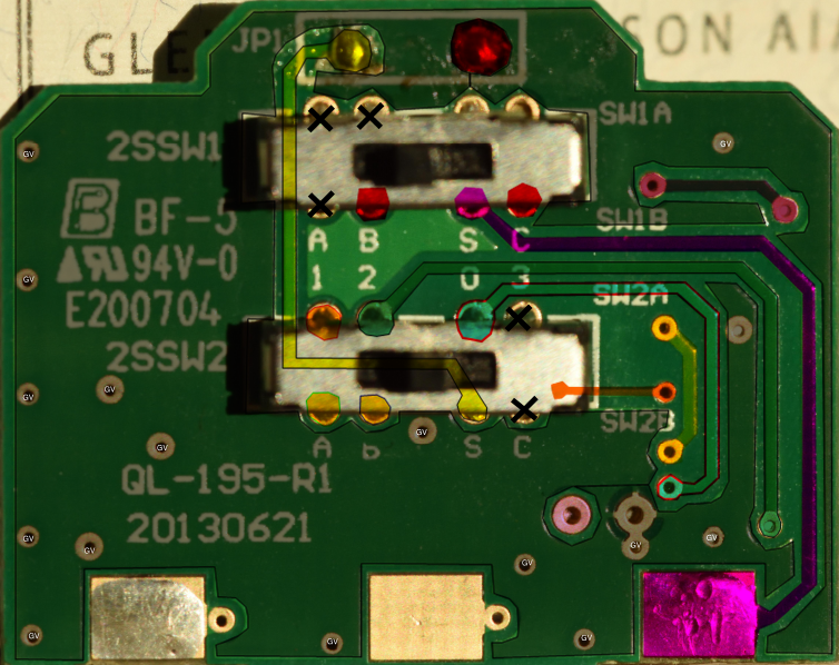
During this process of figuring out the power supply, and what was going wrong, I actually ended up fully reverse engineering the original otamatone circuit so I could see why I was frying things. The results of that are attached below as a sch Ki-CAD schematic file and as a pdf. This is, as far as I can tell, an accurate representation of the otamatone's original circuit, but I am not sure if I was able to accurately measure the capacitance values I have shown. I hope to revisit that some day and update things if I find my initial try was wrong. The capacitance coupled with the variable resistor (and some other fixed resistors on board) is responsible for the frequency of the output signal, so messing with the values will allow you to modify the circuit to generate different frequency ranges than the original hardware fi you're so inclined.
Now armed with the knowledge of how the original circuit works (a push-pull RC transistor oscilator driving the speaker output transistors high and low) I was able to supply power to all 6 heads simultaneously and control them with the now-functional control board I had hacked together. I also took the step of completely removing the control boards and giving them 5-pin connectors so that I would be able to test things and work on them without disassembling the head. The heads now only contain the speaker and the two speaker wires for ease of use, but the sound is still generated entirely using the original circuitry.
The current working prototype has a lot of wire connecting the otamatone control board, to the speaker wires in the head, to the power supply, and to the badly designed PCB control board I made with the Teensy and digital potentiometers. I plan to remove almost all of this extra wiring so that the control board will take the Teensy USB connection, a power supply connection, and output only the two speaker wires. I will also have 5-pin headers on the control PCB to plug in the original control boards, or possibly even control boards of my own design in the future. This will all be covered when I finish designing and building it in part 3 of this series.
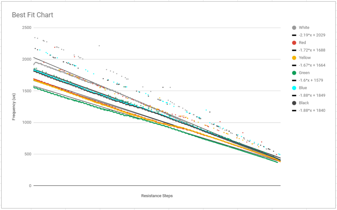
The last step that came about in getting the prototype to work was to add the ability to mute the heads during the boot-up sequence. I was hoping that I would be able to find a neat equation that would map close enough to the note frequencies that the bootup testing sequence would be unnecessary. Unfortunately after testing, the actual frequency response is not linear enough to be able to do that reliably, and it varies for every head. You can see the best-fit slope data for the heads in the chart below labeled 'Best Fit Chart'.
Since replacing the bootup sequence programatically wasn't an option, and the values were volatile enough that I could not store them between boot cycles, I opted for adding a 1000 ohm dummy load in parallel with the speaker (and also with the volume limiting 10 ohm resistor you can see in the original schematic depending on where the power switch is set) and I added a switch to disconnect the speaker so it could measure the frequency without me having to hear it sound off every frequency every head can play. In the next revision of the board, i will add extra optoisolators so that this can be done in code instead of with the hardware switches.
A final note for hardware: When I started I was using two 50k digital potentiometers to emulate the original 100k resistor strip that came with the otamatones. I have since switched to using a 100k and a 50k together, as it increases the range of MIDI notes that can be played by each head. With the original configuration, the notes between low, mid, and high ranges would often not be able to completely overlap, leaving a few notes that no head was able to play. By increasing the resistance, this extended the note range enough to mitigate this problem. Since I have a 50k in there, i oscilate it between steps 0 and 1 across every step of the range of the 100k pot and that allows me to maintain the same resolution for each step as I had before with two 50k digital pots.
Working Prototype:
Finally, after going through all that mess, I was able to get the thing programmed, handling MIDI notes reasonably well, and actually playing songs. See the video below for proof that this thing was (more or less) working at least once. The next hardware revision will be a nearly complete rebuild, so it may not work again for a while.
My next steps will be to redesign the PCB, using an I2C PCA9685 controller to control multiple servo motors that will allow me to actuate the mouths of the heads corresponding to MIDI note velocity. I'm also planning on adding hardware MIDI support in addition to USB MIDI, as well as a header for the ability to add addressable LED lighting to the project.


