oMIDItone - Part 3
Date Published: 2023-11-08

The oMIDItone was progressing steadily through late 2019 into early 2020, and just as everything was finally coming together, this annoying global pandemic called Covid-19 turned up, causing me to become to reclusive hermit and put the whole project into a plastic bin under my desk for the last few years. Unfortunately, I didn't write this blog post at the beginning of the pandemic, so most of the specifics of the process that led to the current state of the project are lost to time. Instead of telling you how I got here, for this blog post I will instead note the current state of the project, and my plans for the future of the oMIDItone.
The State of the oMIDItone:
In my last blog post I mentioned that I would be designing a new 6-head oMIDItone PCB which would take all that I had learned when initially getting the MIDI-controlled Otamatone circuitry working. I have since completed this new 6-headed oMIDItone PCB. In addition to being able to make all 6 heads output audio at once, this PCB allows me to use some face-grabbers with servo motors to open the mouths of the Otamatone heads as notes play, and it has fancy LED lighting effects that are triggered by the MIDI notes sent to the device. The design for the controller PCB is available at the bottom of this post for download (and it's also in the GitHub repo). It requires a teensy 3.2 to run everything, and those aren't the easiest devices to get your hands on at the moment, unfortunately. Looking at the PCB, I noticed that I also ended up soldering in discreet transistors instead of using the optoisolator chips for some reason. I don't remember if it was because the optoisolator chips weren't able to switch fast enough, or if I just didn't have them on hand and wanted things working ASAP. Regardless of the reasons, the discreet transistors are working as intended in place of the optoisolators, so I will likely use them on any future revisions as they cost a fair bit less.
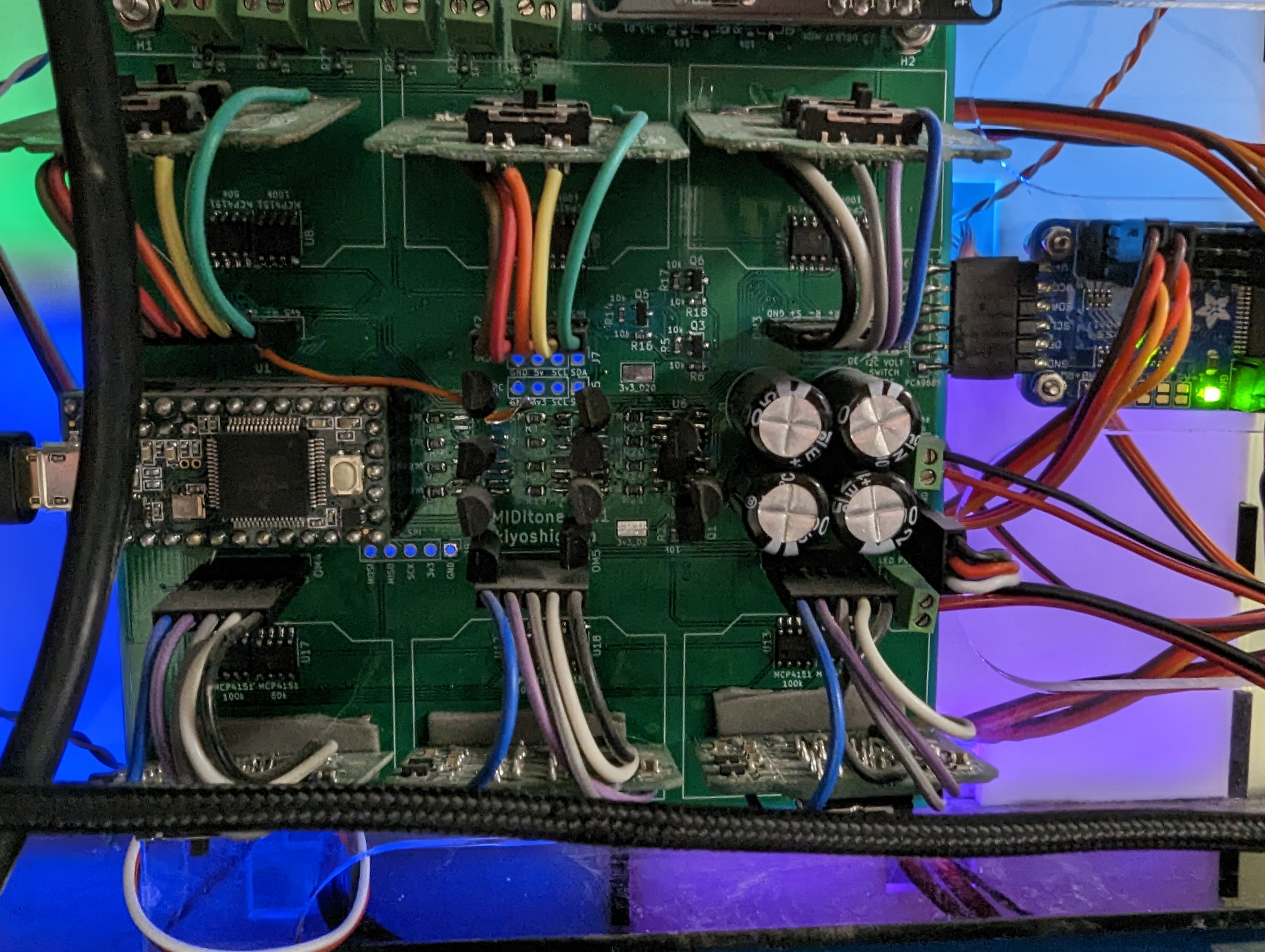
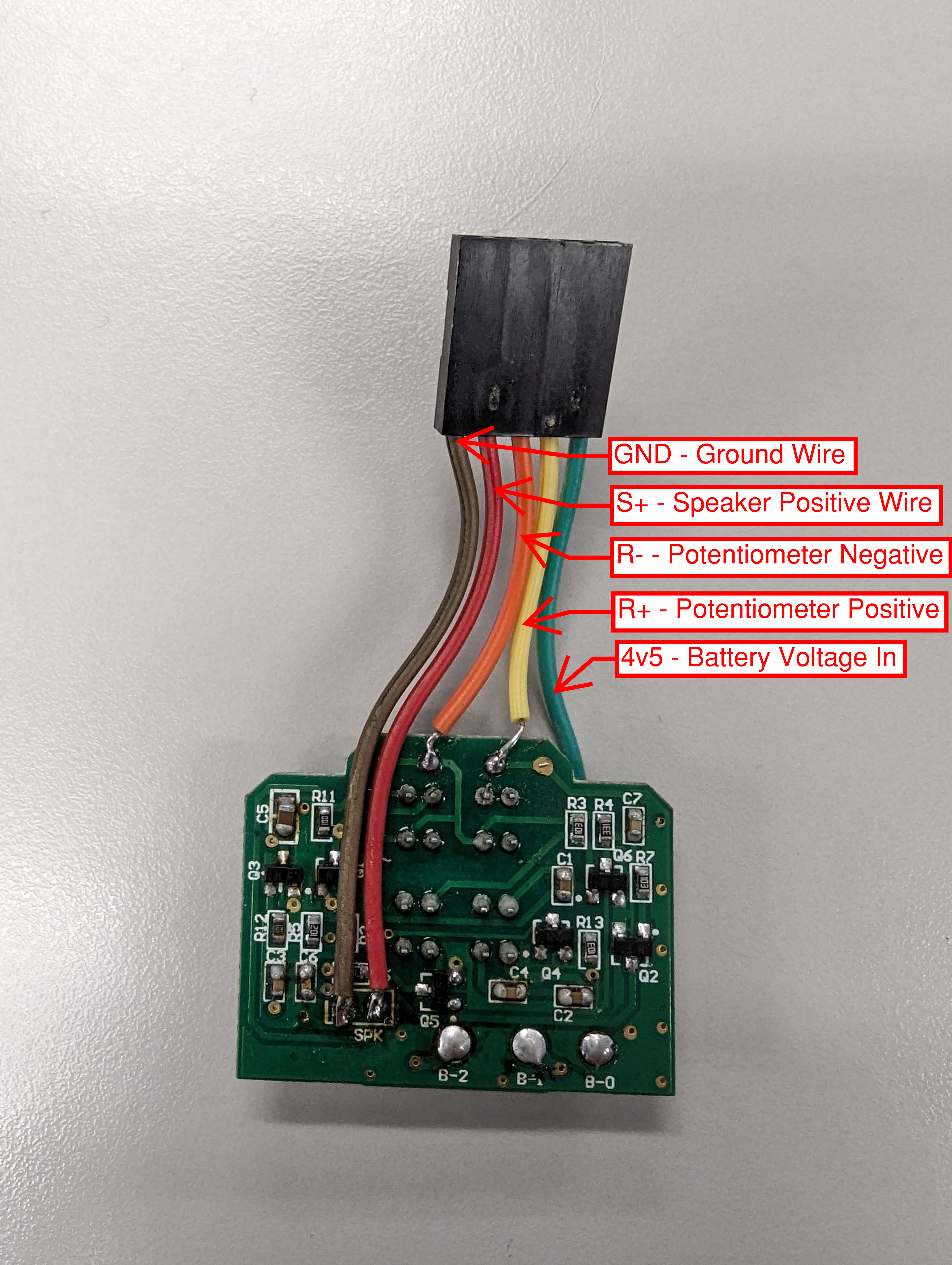
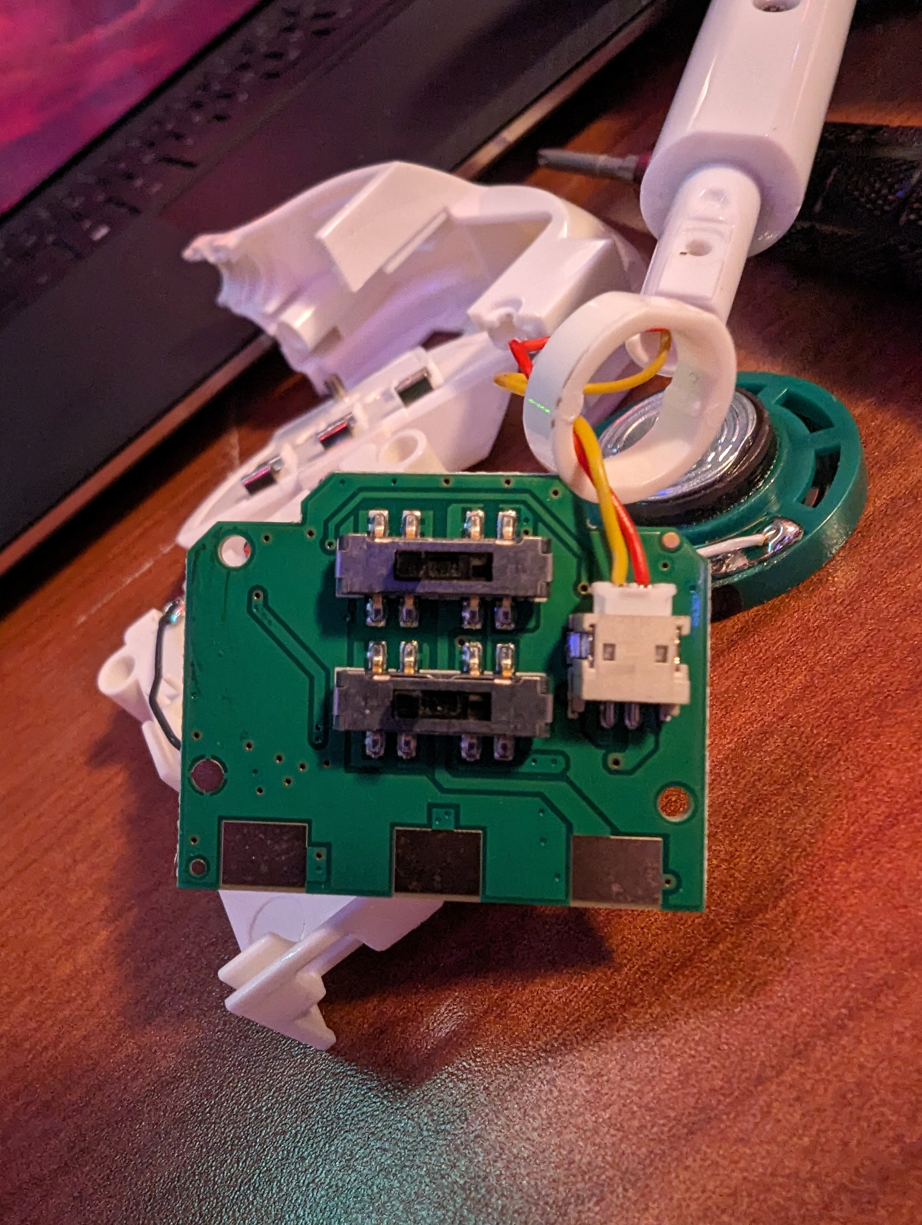
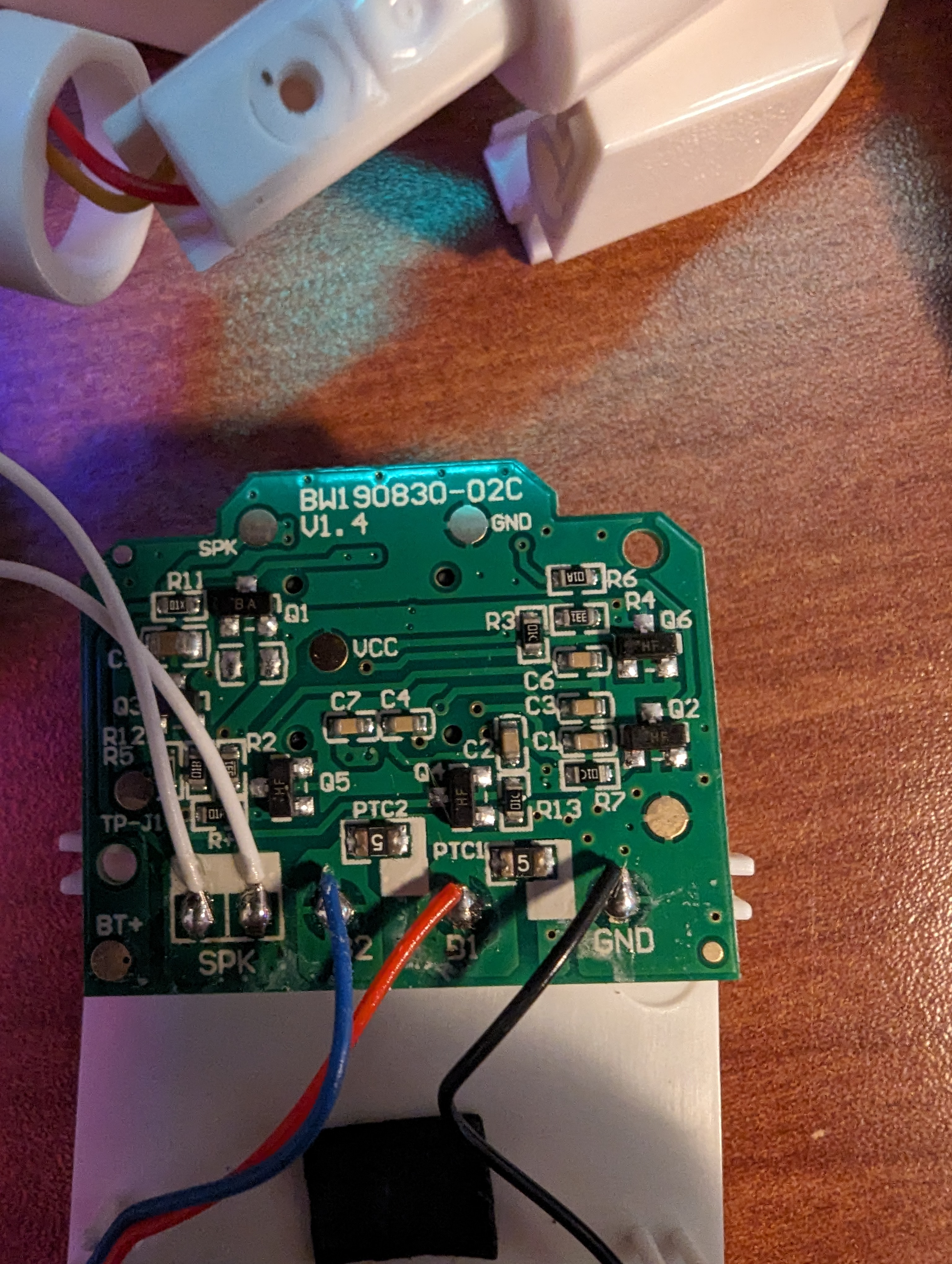
The new PCB layout integrates the original Otamatone head control PCBs directly into its design. You need to solder a total of 5 wires onto the PCB in order to connect it to the headers in the PCB I created for this project. You also need to remove the thermistor that is being used as a thermal fuse from the battery connector and solder it onto the PCB or the heads can burn out their transistors and/or speakers. This thermistor is hidden in the very front of the plastic Otamatone housing, and it can be easily missed if you don't disassemble the entire head. You can see where the wires attach to the original Otamatone PCBs I am using in the photos below. Note that I've also included some photos of a newer revision of the Otamatone PCB below, though without the wiring. You will still need to attach the 5 wires to appropriate points on the new PCB. These new PCBs also have SMD thermistors soldered directly onto them, so if you use them you won't need to disassemble the battery enclosure to get your hands on the thermistor like I did with my older PCBs. The new PCBs also have a fancy plug-in connector for the two resistor pins, so you could re-use that connector for your wiring if you wanted.

You can see a video of the whole device working here:
Those of you that are not tone-deaf may have noticed some issues with the way the device sounds when more than one head is playing notes in harmony. I was bothered by this, and after a fair bit of testing with a logic analyzer and oscilloscope, I have determined that the primary reason it sounds bad when multiple heads are playing is that the digital potentiometers I am using have a minimum increment size of ~195 ohms per step. This step size, it turns out, is not small enough to accurately hit the exact note frequency I am looking for. Because each head has slightly different values for their resistors and capacitors, each head tends to settle on a slightly different frequency when attempting to play the same note. Depending on the head, this can be anywhere from 1-2 cents off the desired note, up to 13 cents in the case of the red head. This results in the unfortunate sounds that tend to occur when most of the heads are playing at the same time. The problem gets worse the higher the notes are, as smaller changes in resistance cause larger frequency changes.
Another issue with the current design is that the heads are either entirely on or off. They can only scream at the top of their lungs, or be silent. This can be fine for some songs, but the lack of dynamic range can drown out the sounds that should be present, while allowing notes that would normally fade into the background of a song to jump to the forefront.
You may have also noticed that everything is built into a nice enclosure. I've got all the design files for the enclosure included at the bottom of the post (and they're also in the GitHub repo). I would not recommend building the enclosure with face grabbers exactly as shown, though. The design for the face grabbers is using tiny servos that don't quite have enough torque to squeeze the faces as much as I would like, and since they are operating right at the edge of what they can do, I've had issues with them burning out occasionally and needing to be replaced. The LED lighting is also a big pain to wire, and if you need to make any modifications to things, you need to disconnect all the LED and servo wiring from the PCB before you can open the back panel to get access to anything. Since each servo needs to be individually calibrated to operate in the correct position, it's a big pain to disconnect and reconnect them all in the correct order.
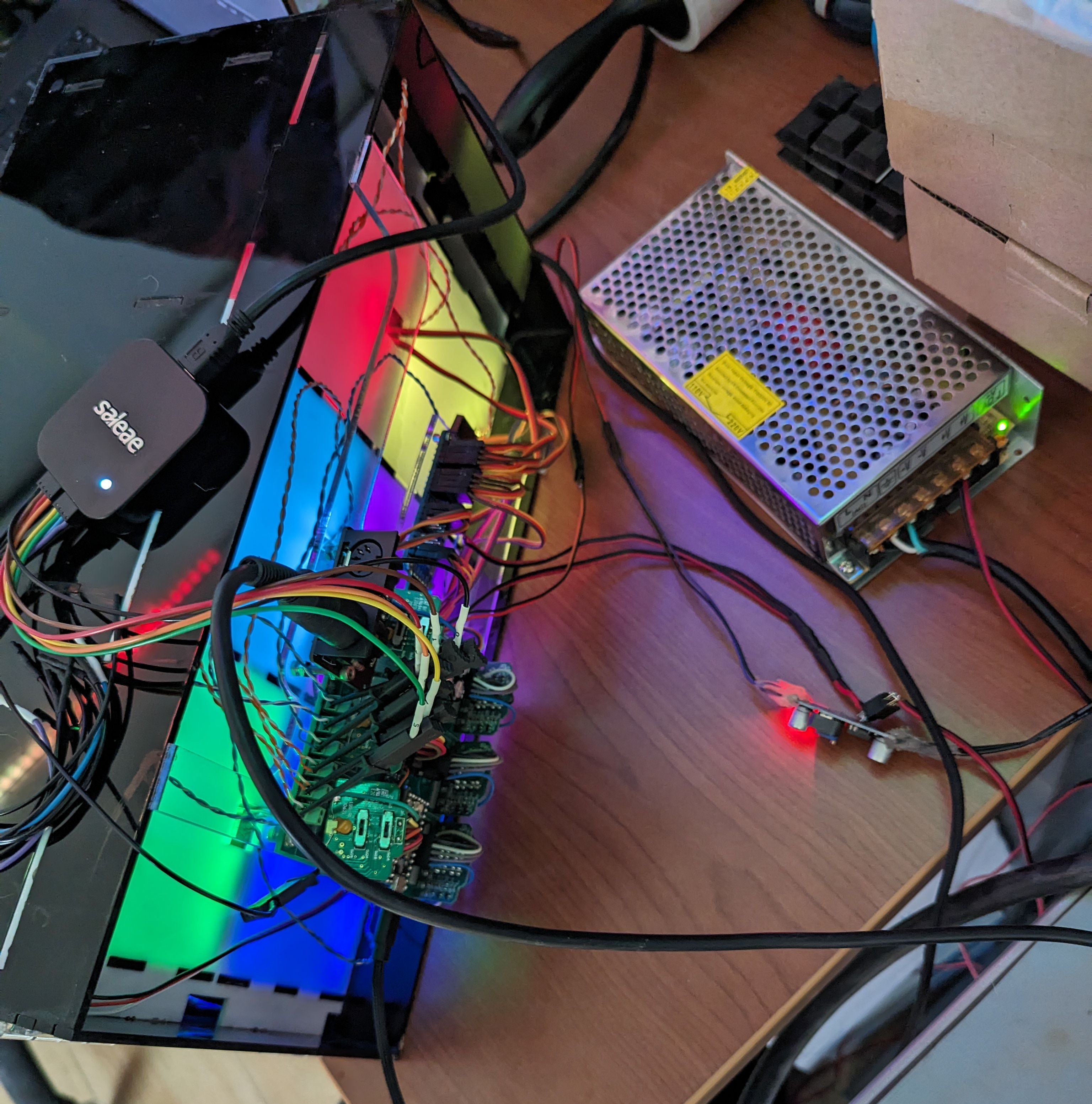
Another fun thing about the current design is that it currently requires three separate power supplies. I've got a big metal boxy 5V power supply that is being used to power the LED lighting and servo motors, as well as a small switching mode power supply that is powering all 6 heads' analog circuitry (to keep the noise of the motors out of the audio oscillator circuit), and finally the teensy 3.2 (and subsequently the hardware MIDI board) is powered directly via a USB connection. This results in a big tangled mess of cords that sit behind the neat-looking box where the heads reside. You need to plug in all three of these power supplies every time you want to use the oMIDItone in its current form.
All the aforementioned problems aside, the oMIDItone v2 is more-or-less fully functional at this point, and the setup works with both software MIDI over the teensy's USB connection and hardware MIDI inputs from the expansion board I've attached to the PCB on the back. The lighting effects and servo animations can be controlled via MIDI control codes, and the device plays any MIDI files you feed it, though how it sounds is highly dependent on the file and how many harmonies it's attempting to play at once.
The Future of the oMIDItone:
So where does the project go from here? My plan is to leave this incarnation of the oMIDItone exactly as it is, and to work on a new version of the oMIDItone to bring the project forward into the future. The new version will have the following upgrades (in no particular order):
-
Each head will become a discreet device. Each individual head will be run on its own PCB / MCU. It will be able to receive MIDI commands directly, and will have its own enclosure, face grabber, and lighting controls. I will set up each head to receive on a specific MIDI channel. The channel selection will need to be either hardware or software configurable.
-
I will build a separate central controller PCB that will be able to handle sending notes from various MIDI input sources out to multiple heads automatically so that I can have the same automatic holistic song playback that the current single-PCB 6-headed design provides. I may even design other automated MIDI instruments and devices that can connect to this central controller such as drum machines or discreet lighting controllers so that any MIDI file can result in an automated musical experience.
-
I will be using different digital potentiometers with smaller step sizes to allow me to better tune the heads to the desire frequency, hopefully eliminating the terrible-sounding harmonies the current system produces. The same chipset I am currently using also has 5k ohm potentiometers available that should allow for a resolution of 19.5 ohms instead of 195 ohms, which will hopefully produce much more exact frequency outputs on a per-head basis.
-
Power to each individual head unit will come from a single source, and be stepped down and split up on each individual board's PCB. I will provide in-circuit isolation for the analog power, and my intent is to use a step-down voltage regulator to provide more stable and consistent voltage to each head compared to the switching mode power supply shared among the 6 analog synthesizer circuits I am using now. This will require some additional testing in order to verify that everything will work as intended and that the face-grabber motors are not causing any issues with the analog circuitry.
-
I will be experimenting with populating my own Otamatone analog circuit boards that can be used in lieu of removing the control board from a real Otamatone. Since real Otamatones now cost $40 USD at the time of writing this blog post, it seems like a prudent financial decision to integrate the analog oscillator into my own PCBs.
-
I will also be experimenting with emulating the output of the Otamatone's analog circuits, as it is clear from the oscilloscope readings of the output that it is basically just a square wave oscillator. If the output sounds effectively the same as the analog circuit, I would no longer need to worry about constantly adjusting the potentiometer resistance to account for slight changes and harmonics present in the analog synthesizer circuits and could simply use the MCU clock to ensure that the frequency is being correctly maintained. If it turns out that the 'tone' of an Otamatone can be faithfully recreated using only a normal square wave and mouth manipulations, then that eliminates a lot of difficult problems caused by using the original analog circuits.
-
The current face-grabber design is underpowered and the servo motors are quite noisy and prone to burnout. I am planning to experiment with a new design that employs a stepper motor with a microstepping driver to reduce the noise, and hopefully provide enough torque to adequately open the mouth in a more analog manner. If I can get the mouth movements to be more fluid and quieter, I would be able to implement better mouth animations, which effect the sounds produced by the Otamatone heads quite significantly. It should allow for better expression, and can be configured based on MIDI note velocity to change how the mouth reacts to any specific input.
-
I also want to add a small amplifier circuit that can be controlled via MIDI note velocity to reduce the volume of the output of each head to match the MIDI input's requirements. The current 'screaming or silent' operation mode of the Otamatone heads does not allow for an adequate performance of the MIDI files I have been using. Hopefully the combination of volume control on the output, as well as better face-grabbers and mouth expressions will allow for a much better show.
I'm sure as I work through implementing these changes, I will come up with some better ideas and find new problems that need to be addressed. I am especially interested in seeing if people will be able to tell a difference between an original Otamatone circuit, an Otamatone circuit made by me via reverse engineering, and a generic square wave output from a microcontroller. Regardless, I look forward to making lots more automated musical devices in the future. Hopefully it will be less than 4 years between updates next time.


